 04-29-2015, 12:56 AM
|
#1 (permalink)
|
|
EcoModding Apprentice
Join Date: Apr 2015
Location: USA
Posts: 148
Thanks: 5
Thanked 50 Times in 43 Posts
|
Big Van Kammback/template help
I'm using Internet Explorer and I think that's why the template never works for me? I use my pc at work and at home use a company laptop so IE is it for me, for now.
I think I understand the interactive template tool but want to be sure.
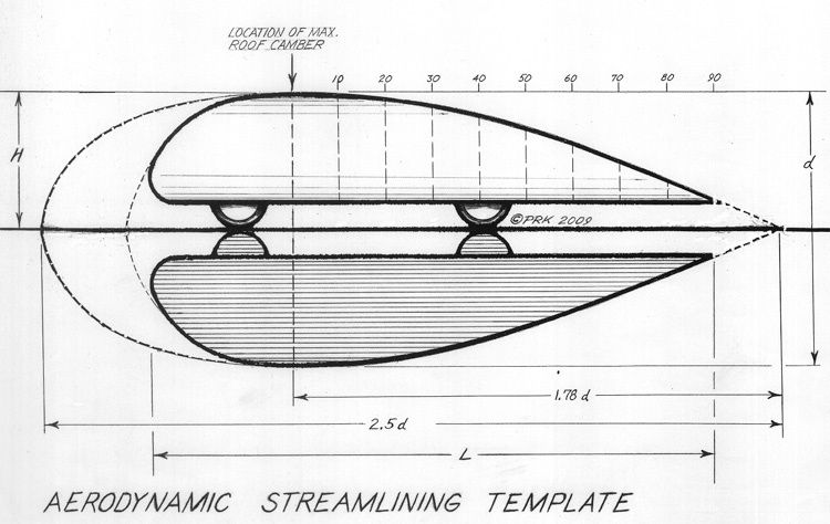
I also reference this picture 
The numbers across the top start at 0 and count up in increments of 10, this is percent of 1.78d (kammback length) after the point of max camber, right? (these numbers appear at the bottom of the interactive tool) That's why they stop at about 90% which would be 1.78 d, right?
D is 2H, which is overall height, right? and 2.5d represents the affected zone?
The number across the top (of the interactive tool) start at 0 and go up 3.5, then 7.5, 12, 15, 18.5, etc. These are degrees of taper, right? (meaning the flat roof is zero and 3.5 is 3.5 degrees down from zero, etc)
Overall length of van is 18' 9-15/16" and height is 7' 1". Treating the rear upper edge of roof as point of maximum camber (because the roof is essentially flat front to rear and is over 15' long) and assuming I run a kammback length (total stickout, not surface length of panels) of 20% of overall height (1' 5") should its shape be the same as one 30% of overall height (2', 5-1/2")? I know its degree of taper should change, anything else? Given that length is waaay longer than height (more than 60% difference) but height and width differ by only about 5%, should I extend the kammback length to some other proportion? Would its effectiveness be significantly greater at 40% than 15% of h?
I've read KB bottomside angle should be 2.5°, is this correct regardless of its length?
Obviously I can't extend my van 1.78 times double its height (which equals over 12.5 feet!) past its true point of maximum camber (the upper most corner of its very bluff rear end) so where should I end the Kammback? Obviously longer is better and there is a point of negligible gain (too short to matter) but where should I expect to find the point of maximum drag reduction per length?
I think my absolute max will be something around 30" total stickout. Remember, I'm starting with a vehicle that's barely under 19' long. Standard parallel parking spaces are 20'. Think about that and the fact that I parallel park basically daily at the busiest hospital and 2nd largest college campus in my state and that I live in my state's largest city. I'd like to get something effective that only hangs back 20-24". State law here prohibits anything extending more than 3' beyond the front bumper. (just noting that here since I found it and may want to find it again)
For my own reference I've worked up the little chart below for rise/run:
0.5° = 1" / 114.6"
1.0° = 1" / 57.29"
1.5° = 1" / 42.96"
2.0° = 1" / 28.64"
2.5° = 1" / 23.86"
3.0° = 1" / 19.08"
3.5° = 1" / 16.69"
4.0° = 1" / 14.30"
5.0° = 1" / 11.43"
10.° = 1" / 5.671"
15.° = 1" / 3.732"
In other words, to get a 15° line from the van's corner you affix a straight line (aluminum concrete screed probably) to it's roof and measure back 3.732" and attach a block 1" thick, measure back 7.464" and attach a 2" block, 11.196" gets a 3" block, and so on. The line connecting the blocks' lower front-facing corners is a 15° line. I'll go about it a little differently than that but you get the idea.
I think I may actually try fiberglassing something up on a hitch mounted stinger. I know it'd be a ton of work and not especially light (by comparison to chloroplast) but it'd be a fun challenge and could be used for future molding or even a swing-away storage pod?!
Last edited by mwilliamshs; 04-29-2015 at 06:11 PM..
|
|
|

|
 Today Today
|
|
|
|
 Other popular topics in this forum...
|
|
|
|
 04-29-2015, 03:17 AM
|
#2 (permalink)
|
|
Master EcoModder
Join Date: Aug 2012
Location: northwest of normal
Posts: 29,418
Thanks: 8,367
Thanked 9,125 Times in 7,534 Posts
|
Yes—You're getting most of the Template.*
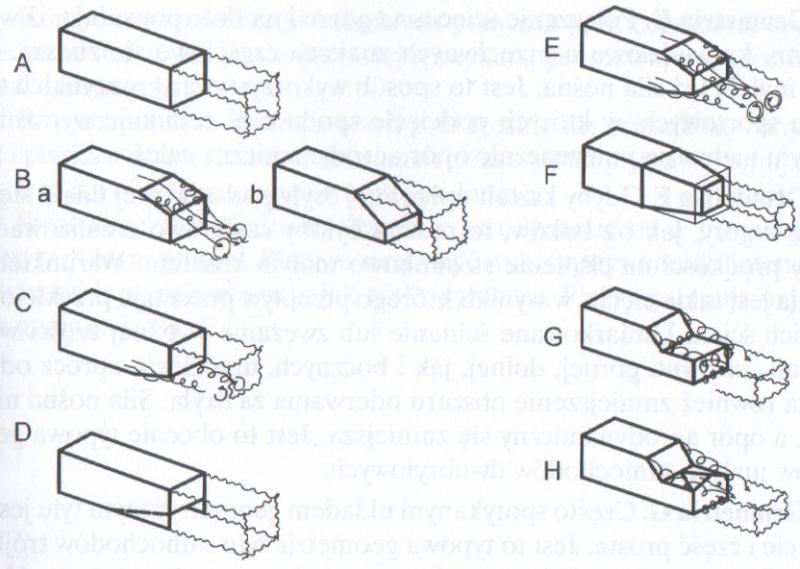
...except the most important thing—it's a half-body of revolution in section, IOW a half circle sitting on the ground. You've got a square. Consider these alternatives to the half-zepplin:

You are at A and you want to get to F. There are interesting alternatives for a hitch mount at G and H. No vortexes is better.
The payback for the added length is linear. 10% gets you 10% and so on. 10% gets you 5mpg. Or something; but a 100% boattail might get you 100% better mileage—40 to 80mpg is believable—but it's a lot of pain to drag one around, as you've seen. So you pick a percentage.
*What you've called "affected zone" is probably less meaningful than Fineness Ratio—the ration of length to maximum camber, which I think of as at 30%/70% of length. Nothing much happen before the point of stagnation: think about how water wraps around the bow of a ship.
Edit: These shapes aren't sliced with a ground plane, but should give the same Cd for a given cros-section.

The biggest difference is the rounded shapes have better cross-wind performance.
Last edited by freebeard; 04-29-2015 at 04:04 AM..
|
|
|

|
 04-29-2015, 03:25 AM
|
#3 (permalink)
|
|
EcoModding Apprentice
Join Date: Apr 2015
Location: USA
Posts: 148
Thanks: 5
Thanked 50 Times in 43 Posts
|
Quote:
Originally Posted by freebeard


You are at A and you want to get to F. There are interesting alternatives for a hitch mount at G and H. No vortexes is better.
The payback for the added length is linear. 10% gets you 10% and so on... |
Gotcha and THANKS. I knew the image i posted was round side-to-side but I hadn't yet seen the boxes. Much more applicable. F is what I had in mind. I can't tell much difference in G and H. I think H has a peaked upper side but is the result better or worse than G? I wish Ba and E had the square like the others for comparison.
So a 10% extension, assuming a perfect execution, etc, can return a 10% reduction in drag?! Seriously? Had no idea it was that good. So a perfectly crafted, perfectly long boat tail can almost entirely eliminate drag (except that which is created by friction, a poorly designed nose, etc)?
Last edited by mwilliamshs; 04-29-2015 at 03:35 AM..
|
|
|

|
 04-29-2015, 03:09 PM
|
#4 (permalink)
|
|
Master EcoModder
Join Date: Aug 2012
Location: northwest of normal
Posts: 29,418
Thanks: 8,367
Thanked 9,125 Times in 7,534 Posts
|
Quote:
|
So a 10% extension, assuming a perfect execution, etc, can return a 10% reduction in drag?!
|
Yes, but not total drag reduction. Just the reduction that would obtain if it was extended completely. And the shape is completely dependent on the 30% of forebody. Here's aerohead explaining:
Quote:
*The streamline body which the 'Template' is based upon has Cd 0.04
*When the body is brought into 'ground reflexion'(Rumpler/Prandtl) it jumps to Cd 0.08.
*When you cut away for ground clearance,you get a car body of Cd 0.08.
*When you add wheels and tires the drag jumps to Cd 0.12-13.
-------------------------------------------------------------------------
*The 2.5:1 streamline body of the 'Template' has zero separation
* As a car body,the Template' will have no separation.
*If you make the aft-body steeper,it violates W.A.Mair's research on aft-bodies,which found 22-degrees to be the max angle air will follow without separation and vorticity.( Hucho allows 23-degrees ) (I'm conservative @22-degrees).
|
http://ecomodder.com/forum/showthread.php/biggest-gains-back-19906-4.html#post280363
______
I found a quote where aerohead explains the Template in general:
Quote:
5:1
The 5:1 L/D ratio is for the 'apparent' ground reflection body,measured at the ground plane.Along with it's sister image below the ground it forms the 2.5:1 streamline body.
A car and it's reflection below the ground is the premise for evaluating it's aerodynamics.
The concept was first realized and introduced by Paul Jaray and gained traction after Ludwig Prandtl's and Edmund Rumpler's wind tunnel work.
The original 'Template'-C illustrates this concept.
Paraphrasing Hucho:" the low drag body is represented by the streamline body and it's reflection below the road surface."
I have cut away the ground clearance of the body based upon SAE 'approach,ramp,and breakover clearance angles.
If you extrapolate the aft-body out and down to the ground plane,it creates the aft-body of the 2.5:1 streamline body,never exceeding Mair's 22-degree angle.
I've essentially ignored the forebody,as mentioned in the 'Template' thread,as Hucho recommends we concentrate on the back of the vehicle for streamlining purposes.
|
http://ecomodder.com/forum/showthread.php/honda-insight-tail-extension-project-13533-47.html#post319931
It sounds like you looked closely at A-F, because you see questions. Notice that F is the only one with plan taper and the mess that E is in comparison.
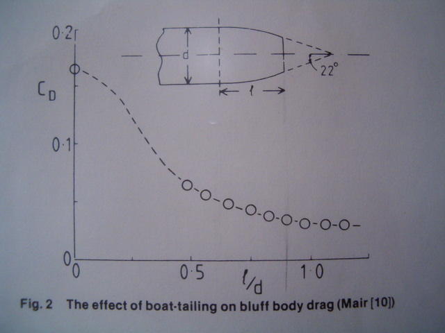
Also, aerohead mentioned Mair; so here's a look at his work:

Relative perfection starts at l/d of 0.5; that's how sharp the curvature is. Once again truncations are possible, so that's two ways of accommodating necessity.
|
|
|

|
 04-29-2015, 04:34 PM
|
#5 (permalink)
|
|
Master EcoModder
Join Date: Jan 2008
Location: Sanger,Texas,U.S.A.
Posts: 16,534
Thanks: 24,520
Thanked 7,436 Times in 4,817 Posts
|
tails
__________________
Photobucket album: http://s1271.photobucket.com/albums/jj622/aerohead2/
|
|
|

|
|
The Following User Says Thank You to aerohead For This Useful Post:
|
|
 04-29-2015, 05:36 PM
|
#6 (permalink)
|
|
EcoModding Apprentice
Join Date: Apr 2015
Location: USA
Posts: 148
Thanks: 5
Thanked 50 Times in 43 Posts
|
Quote:
Originally Posted by mwilliamshs

...where should I expect to find the point of maximum drag reduction per length?...
|

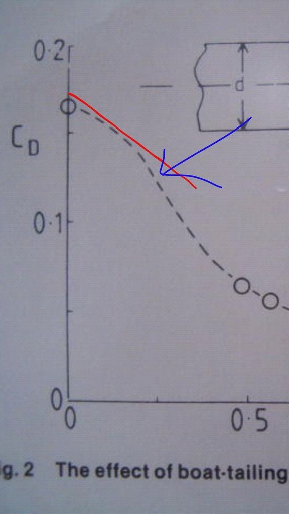
Looks like max benefit per length is at the point of the blue arrow which appears to be exactly .25 (x axis). Of course that length on that diagram isn't universal for all others but it's what I'm hoping to find
My h = 85", so d = 170", 1.78d = 302.6"...how do I find L? Is it 1.78d + body - 10%? That's 302.6" + 225" = 527.6" - 30.26" = 497.33" (~ 41' 5"!)
So IF (bigun) I'm interpreting all of that right, .25 of 1.78d is the tip of the blue arrow and IF that's accurate to the van I need a kammback of 302.6/4 = 75.65" to reach that .25 arrow.
BUT...
That diagram actually shows L as tail length and D as height, so L/D = .25 is the same as 4L = 1D. My height(D) is 85" so .25D = just 21.205" for that blue arrow. I like Mair!!
BUT...
Scratch that. Reread it. D = 2h still. 170/4 = 42.5" tail length for .25 l/d. Still not unimaginable.
At that length, a tail with 4 straight sides and a top taper of 15°, side tapers of 15°, and a bottom taper of 2.5°, would have back-edge dimensions of 57.25" wide and 71.83" tall, call it 5' x 6'.
Last edited by mwilliamshs; 04-29-2015 at 07:09 PM..
|
|
|

|
 04-29-2015, 07:03 PM
|
#7 (permalink)
|
|
Master EcoModder
Join Date: Aug 2012
Location: northwest of normal
Posts: 29,418
Thanks: 8,367
Thanked 9,125 Times in 7,534 Posts
|
No, scratch the whole thing. You've found the maximum rate of change of Cd, a second order thing. Minimum drag, Cd, is the floor of the curve out to the right where l is overunity to d.
|
|
|

|
 04-29-2015, 07:07 PM
|
#8 (permalink)
|
|
EcoModding Apprentice
Join Date: Apr 2015
Location: USA
Posts: 148
Thanks: 5
Thanked 50 Times in 43 Posts
|
Quote:
Originally Posted by freebeard

...You've found the maximum rate of change of Cd...
|
Yeah that's what I wanted: most gain for shortest tail. A shorter tail gains less overall and a longer tails gains less per inch.
Maximum rate of change = sweet spot.
This is not a maximum effort, win at all costs thing for me. Starting with such a BIG vehicle means I can't go whole hog with a boat tail and such poor aerodynamics means the low hanging fruit should yield big percentage points.
2mpg means twice as much to the guy getting 15 mpg as to the guy getting 30. Hope my objective here makes sense
Last edited by mwilliamshs; 04-29-2015 at 07:46 PM..
|
|
|

|
 04-29-2015, 08:19 PM
|
#9 (permalink)
|
|
Master EcoModder
Join Date: Aug 2012
Location: northwest of normal
Posts: 29,418
Thanks: 8,367
Thanked 9,125 Times in 7,534 Posts
|
I see where you're headed.
85" inches across the flats? x.25 would be 21". Or it could be more complicated, the distance on the diagonal is 85x1.42.
Now you have a 2Dline in space, effectively a scaled-down version of the typical cross-section. You can bridge to that with either an curved panel, a flat panel or an instepped box. Compare that line to the door-swing of the rear doors or hatch.
|
|
|

|
 04-29-2015, 08:28 PM
|
#10 (permalink)
|
|
EcoModding Apprentice
Join Date: Apr 2015
Location: USA
Posts: 148
Thanks: 5
Thanked 50 Times in 43 Posts
|
Quote:
Originally Posted by freebeard

...85" inches across the flats? x.25 would be 21". Or it could be more complicated, the distance on the diagonal is 85x1.42...
|
No idea what all ^that^ means.
Van is 85" tall from ground to rooftop. That's H. 2H = D so D = 170" and Mair's graph shows .25 on a scale of L/D (x axis) as the point of greatest cod reduction/length of tail so .25 x D = L. 170/4 = 42.5. That's L, length of tail, which should return greatest gain in reduction of cod for its length. An approximation and WAG to be sure, but best I've got for now.
I've got no room for anything further back than 33" or so. I'll build what I can fit and know there's more to be had with a longer tail. If instead of 42.5 I'd found something like 32" I'd feel better and if I'd found that gains peaked at 18" I'd just build to that length and stop.
A 15° line drops 11.375" over a run of 42.5" and my roofline is about 10.5" above the tops of my rear windows so the tail's top side shouldn't be intrusive at all. With tinted windows I bet painting the flap's inner edges black would make that 7/8" of overlap totally unnoticeable.
Last edited by mwilliamshs; 04-29-2015 at 11:26 PM..
|
|
|

|
|