01-16-2012, 01:57 PM
|
#31 (permalink)
|
|
Aero Wannabe
Join Date: Dec 2007
Location: NW Colo
Posts: 738
Thanks: 705
Thanked 219 Times in 170 Posts
|
Quote:
Originally Posted by aerohead

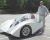
* with respect to the 1971-1974 Citroen SM,I only have a brief article about one that owner Jerry Hathaway ran at Bonneville at 154 mph on an estimated 250 bhp.There is a photo of the car from the side.Under the 'Template' it appears that the flow is compromised at the very top of the backlight,with the rear slope going to 26-degrees (Ford Pinto,Datsun 240 Z). The flow should separate right there with no hope of re-attachment.It's just too steep.
|
Thanks for your additions.
Looking at the Citroen aerodynamics article from a few posts earlier, they mention lowering drag and lift by adding a rear "aerofoil" (spoiler) beneath the rear window on the CX. This reminds me of the Crisis Fighter Pinto with its rear spoiler to improve drag on its too steep back glass.
If Ken tuft tested the back glass on his SM wouldn't the tufts show turbulent flow?
__________________
60 mpg hwy highest, 50+mpg lifetime
TDi=fast frugal fun  https://ecomodder.com/forum/showthre...tml#post621801

Quote:
Originally Posted by freebeard
The power needed to push an object through a fluid increases as the cube of the velocity. Mechanical friction increases as the square, so increasing speed requires progressively more power.
|
|
|
|

|
 Today Today
|
|
|
|
 Other popular topics in this forum...
|
|
|
|
|
01-16-2012, 05:04 PM
|
#32 (permalink)
|
|
Master EcoModder
Join Date: Jan 2008
Location: Sanger,Texas,U.S.A.
Posts: 16,496
Thanks: 24,517
Thanked 7,436 Times in 4,817 Posts
|
CX
Quote:
Originally Posted by COcyclist
Thanks for your additions.
Looking at the Citroen aerodynamics article from a few posts earlier, they mention lowering drag and lift by adding a rear "aerofoil" (spoiler) beneath the rear window on the CX. This reminds me of the Crisis Fighter Pinto with its rear spoiler to improve drag on its too steep back glass.
If Ken tuft tested the back glass on his SM wouldn't the tufts show turbulent flow?
|
I have an article at home for the CX.I want to say that is is by L.J.K.Setright,who road tested the car in Europe.He reported Cd 0.27 for the car,the lowest Cd of any production car of its time.At WOT the car seemed to accelerate for ever,finally topping out in the 120-130 mph region on fairly low horsepower.I don't remember about a rear spoiler,but I do recall that the backlight was configured such that rainwater would be channeled down the center,leaving very good rear vision.
With respect to the SM,I think that Hucho would predict attachment down the centerline of the backlight,but attached longitudinal vortices on the C-pillars.Anything over 23-degrees (Hucho) [22-degrees(Mair)] would be considered a pseudo-Jaray 'fastback',notorious for vortices and their drag.
And it might take smoke to discern the vortices,as they would be 'flying' a bit above the bodywork and might not show with tufts. |
|
|
|
|
The Following User Says Thank You to aerohead For This Useful Post:
|
|
|
01-17-2012, 10:05 AM
|
#33 (permalink)
|
|
Aero Wannabe
Join Date: Dec 2007
Location: NW Colo
Posts: 738
Thanks: 705
Thanked 219 Times in 170 Posts
|
Quote:
Originally Posted by aerohead
With respect to the SM,I think that Hucho would predict attachment down the centerline of the backlight,but attached longitudinal vortices on the C-pillars.Anything over 23-degrees (Hucho) [22-degrees(Mair)] would be considered a pseudo-Jaray 'fastback',notorious for vortices and their drag.
And it might take smoke to discern the vortices,as they would be 'flying' a bit above the bodywork and might not show with tufts.
|
So is it safe to say that we cannot always rely on the tufts, at least as far as the back of the vehicle is concerned? I recall a thread on here about the aerodynamics of the New Beetle and people wondering about why the drag numbers were so bad, even though it had attached flow down to the bumper?? That is why we have the template, right? Exceed its angles at your own peril.
__________________
60 mpg hwy highest, 50+mpg lifetime
TDi=fast frugal fun
https://ecomodder.com/forum/showthre...tml#post621801
Quote:
Originally Posted by freebeard
The power needed to push an object through a fluid increases as the cube of the velocity. Mechanical friction increases as the square, so increasing speed requires progressively more power.
|
|
|
|
|
|
01-17-2012, 01:40 PM
|
#34 (permalink)
|
|
Master EcoModder
Join Date: Dec 2008
Location: Southern WI
Posts: 829
Thanks: 101
Thanked 563 Times in 191 Posts
|
Quote:
Originally Posted by COcyclist
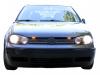
... I recall a thread on here about the aerodynamics of the New Beetle and people wondering about why the drag numbers were so bad, even though it had attached flow down to the bumper??....
|
I wouldn't mind seeing a picture or video of the tuft test in that situation.
It's hard for me to picture why the tufts would lie flat on a surface that has detached air running across it due to the extreme angle of decline.
Jim. |
|
|
|
|
01-17-2012, 03:38 PM
|
#35 (permalink)
|
|
A Legend in his Own Mind
Join Date: Dec 2011
Location: Atlanta
Posts: 281
Thanks: 52
Thanked 91 Times in 54 Posts
|
Quote:
Originally Posted by aerohead
With respect to the SM,I think that Hucho would predict attachment down the centerline of the backlight,but attached longitudinal vortices on the C-pillars.Anything over 23-degrees (Hucho) [22-degrees(Mair)] would be considered a pseudo-Jaray 'fastback',notorious for vortices and their drag.
And it might take smoke to discern the vortices,as they would be 'flying' a bit above the bodywork and might not show with tufts.
|
Thanks for your comments, here, and elsewhere. I put the template over an SM image, and it is not until the very aft edge of the backlight that the angle goes to 24 degrees. At the top of the backlight frame, it is about 11 degrees. I could be off in both cases by a couple degrees. The SM actually rode a little nose-low, I think -- at least the picture I used seemed about like my old one. But clearly the backlight begins to drop away from the template at its forward edge.
I agree it would be interesting to see the whole back end tufted.
It would also be fun to reposition the self-levelling linkage, to raise the rear and lower the front. Makes me wish I still had the car. Somewhere there is probably a fully meshed SM model sitting in someone's CFD machine.
Regards, Ken
Oh, and no insult taken at all re your Nuna post. I enjoy all your posts. |
|
|
|
|
01-17-2012, 04:10 PM
|
#36 (permalink)
|
|
A Legend in his Own Mind
Join Date: Dec 2011
Location: Atlanta
Posts: 281
Thanks: 52
Thanked 91 Times in 54 Posts
|
Quote:
Originally Posted by 3-Wheeler
I wouldn't mind seeing a picture or video of the tuft test in that situation.
It's hard for me to picture why the tufts would lie flat on a surface that has detached air running across it due to the extreme angle of decline.
Jim.
|
An issue with VWs, many old sports cars (including the E-type Jag, which looked streamlined but had a Cd over .4) are the fenders. It's as if they are two cars, one following the other: you bash the air out of the way, and just when it becomes reattached, you bash it out of the way again.
So there is a lot of complexity to the VW story -- it would be interesting to see the flow visualizations. I have a hard time imagining flow attached all the way to the rear bumper. |
|
|
|
|
01-17-2012, 04:49 PM
|
#37 (permalink)
|
|
Aero Wannabe
Join Date: Dec 2007
Location: NW Colo
Posts: 738
Thanks: 705
Thanked 219 Times in 170 Posts
|
Quote:
Originally Posted by 3-Wheeler
I wouldn't mind seeing a picture or video of the tuft test in that situation.
It's hard for me to picture why the tufts would lie flat on a surface that has detached air running across it due to the extreme angle of decline.
|
Jim, I don't recall the EM thread title but it referenced this Autospeed tuft test and diagram:
Browser Warning
__________________
60 mpg hwy highest, 50+mpg lifetime
TDi=fast frugal fun
https://ecomodder.com/forum/showthre...tml#post621801
Quote:
Originally Posted by freebeard
The power needed to push an object through a fluid increases as the cube of the velocity. Mechanical friction increases as the square, so increasing speed requires progressively more power.
|
|
|
|
|
|
The Following User Says Thank You to COcyclist For This Useful Post:
|
|
|
01-17-2012, 06:53 PM
|
#38 (permalink)
|
|
Master EcoModder
Join Date: Jan 2008
Location: Sanger,Texas,U.S.A.
Posts: 16,496
Thanks: 24,517
Thanked 7,436 Times in 4,817 Posts
|
angles
Quote:
Originally Posted by COcyclist
So is it safe to say that we cannot always rely on the tufts, at least as far as the back of the vehicle is concerned? I recall a thread on here about the aerodynamics of the New Beetle and people wondering about why the drag numbers were so bad, even though it had attached flow down to the bumper?? That is why we have the template, right? Exceed its angles at your own peril.
|
The angle thing goes back to boundary layer theory and has to do with too rapid of a pressure rise in the presence of an unfavorable pressure gradient.
Beyond the max camber point of the roof or sides of the car,the air immediately adjacent to the skin of the car is at zero velocity because of viscosity effects of the air.
If the profile of the car is too radical,the boundary layer won't be able to transport kinetic energy in,the flow will be demanded to slow,but it's already at a standstill and it will just lift off the car with air flowing backwards into the void,beginning the eddies which will become full-blown turbulence downstream.
*The streamline body which the 'Template' is based upon has Cd 0.04
*When the body is brought into 'ground reflexion'(Rumpler/Prandtl) it jumps to Cd 0.08.
*When you cut away for ground clearance,you get a car body of Cd 0.08.
*When you add wheels and tires the drag jumps to Cd 0.12-13.
-------------------------------------------------------------------------
*The 2.5:1 streamline body of the 'Template' has zero separation
* As a car body,the Template' will have no separation.
*If you make the aft-body steeper,it violates W.A.Mair's research on aft-bodies,which found 22-degrees to be the max angle air will follow without separation and vorticity.( Hucho allows 23-degrees ) (I'm conservative @22-degrees).
gotta go! hope I didn't muddy the waters. |
|
|
|
|
The Following User Says Thank You to aerohead For This Useful Post:
|
|
|
01-17-2012, 11:35 PM
|
#39 (permalink)
|
|
Aero Deshi
Join Date: Jan 2010
Location: Vero Beach, FL
Posts: 1,065
Thanks: 430
Thanked 669 Times in 358 Posts
|
If I may,

What I think Aerohead is trying to say is, once you get past the front edge of the rear glass, you drop below the template. In doing so, the air cannot remain attached beyond this point due to the curvature of the car dropping away faster than the air is capable filling in.
The 23° limit is the absolute limit if you follow the template out to the end. Anytime you exceed the template curve before that point, you exceed the ability of the air to remain attached.
That said...It's my turn to muddy the water.
I think the flow attachment thing happens in degrees, and the Template optimizes the flow attachment so the pressures are at their best to achieve the lowest Cd. I think the flow remains attached beyond the top of the rear glass, but it is under "stress" and the pressures create a lower than optimum Cd, so it's still good, just not great. More like a grey area is created when you are sub template, until you reach 23°....then it is done, shredded, no more grey area, its over.
Last edited by ChazInMT; 01-18-2012 at 06:16 PM..
|
|
|
|
|
The Following 2 Users Say Thank You to ChazInMT For This Useful Post:
|
|
|
01-18-2012, 08:58 AM
|
#40 (permalink)
|
|
Recreation Engineer
Join Date: Dec 2009
Location: Somewhere USA
Posts: 525
Thanks: 333
Thanked 138 Times in 103 Posts
|
AND the template applies only down centerline (vertical plane of symmetry lengthwise). Away from centerline sides play a role. It's a 3D problem. If the sides taper more quickly then the top, air flows over top and down the sides to fill. If top drops more quickly than the sides slope, air flows up the sides and over top to fill. Flow will establish its equilibrium. Equations will balance. Even without boundary layers, simpler pressure/flow CFD should help here. Tufts help and are more approachable technology.
Last edited by KamperBob; 01-18-2012 at 09:00 AM..
Reason: typo
|
|
|
|
|