03-18-2011, 02:04 PM
|
#31 (permalink)
|
|
Administrator
Join Date: Dec 2007
Location: Germantown, WI
Posts: 11,203
Thanks: 2,501
Thanked 2,589 Times in 1,555 Posts
|
Quote:
Originally Posted by saand

sounds good, also a standard transistor bjt should give you enough current to switch the solenoid, these are often cheaper and easier to get compared to mosfets that will activate off 5v or 3v3. so something like a bc546 or similar device which you should be able to get from any electronics shop.
|
Unfortunately, the starter solenoid is what is drawing the 10A+ at start up. Its powers the mechanism that moves the starter pinion into place and I'm guessing also connects power to the starter motor at the same time. Its a fairly heavy assembly that gets slammed into place. If I have a smaller transistor I'll use it, but I know I have a few mosfets on hand, so thats why I mentioned it.
|
|
|

|
 Today Today
|
|
|
|
 Other popular topics in this forum...
|
|
|
|
|
03-18-2011, 02:44 PM
|
#32 (permalink)
|
|
Master EcoModder
Join Date: Jul 2010
Location: Belgium
Posts: 4,683
Thanks: 178
Thanked 652 Times in 516 Posts
|
Quote:
Originally Posted by Nevyn
Does the manual tranny have some sort of Park/Neutral position switch that you could just tap off of to know when it's in neutral?
|
They usually don't have such a system.
Cars with a start-stop system do have such a system (or similar) to detect wether they are in gear or not.
So it might be or become hardwired in cars of the same model, but only get used on the cars that actually have the stop/start feature.
On most cars, all wiring is in place by default, it just needs connecting or software to set it free.
__________________
Strayed to the Dark Diesel Side

|
|
|
|
|
03-18-2011, 08:31 PM
|
#33 (permalink)
|
|
Administrator
Join Date: Dec 2007
Location: Germantown, WI
Posts: 11,203
Thanks: 2,501
Thanked 2,589 Times in 1,555 Posts
|
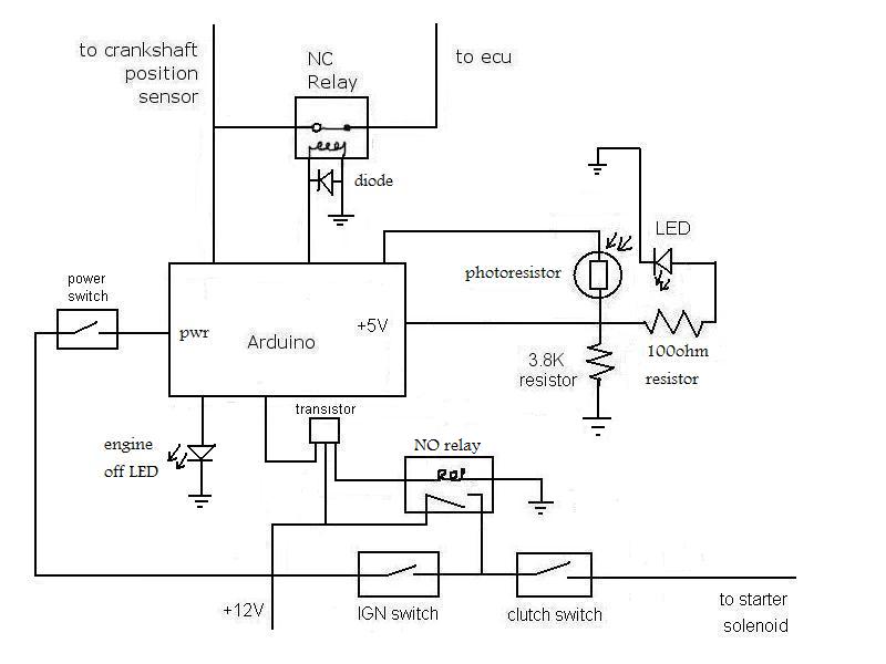
Alright, so I think I finally got it. Good enough for a first go at least. Here is the latest schematic. I cleaned it up a bit so it should be a little easier to read. I've also added a power switch for the mod. Power it down if you don't want it used and all operation returns to normal. I've also added a "engine off" LED to visually show you the engine is off.
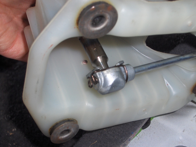
So, I started working on mounting the sensors into the car.
Here is the LED mounted in the shifter housing.
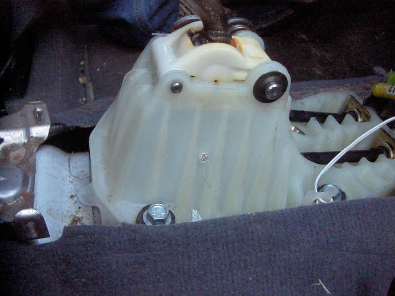
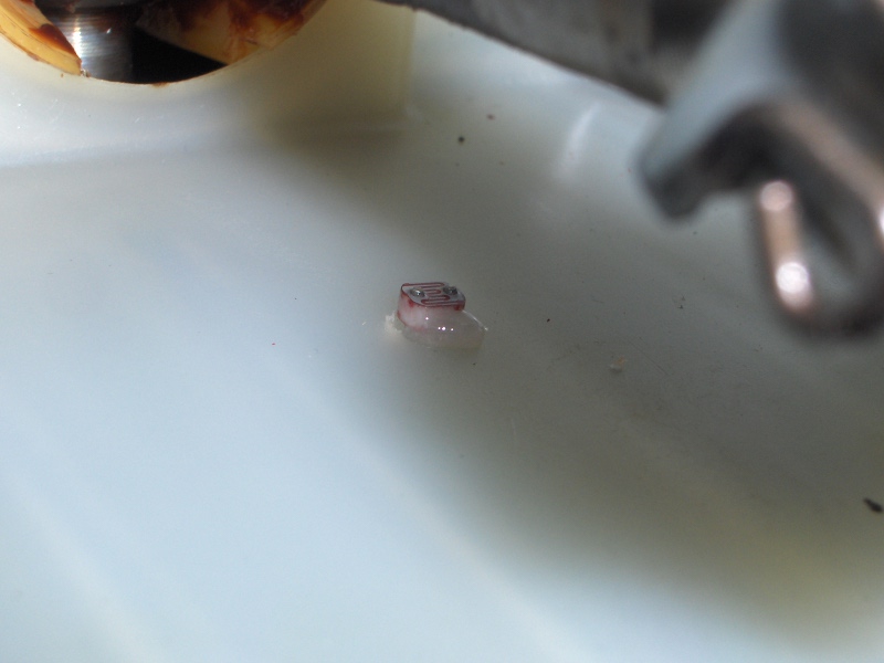
Here is the photoresistor mounted inside the housing. I put a dab of epoxy on it to hold it in place.
With any luck I'll have the rest of the stuff soldered up on a board and into the car sometime this weekend. |
|
|
|
|
03-18-2011, 11:11 PM
|
#34 (permalink)
|
|
Wiki Writer
Join Date: Jul 2010
Location: Melbourne, Australia
Posts: 236
Thanks: 15
Thanked 25 Times in 22 Posts
|
daox,
the schematic looks good to me from a conceptual point of view.
In the event that you have depicted all the components you plan to use you may have an issue or 2
If you have depicted the transistor setup as you intend to use it then it may not work depending on the output of the arduino and type of mosfet.
if you have a high side switching fet (i think it is p channel) it will conduct if the voltage between the gate and the source is below the Vgs specified in the datasheet. It appears that you have connected the source pin to 12v. I assume the arduino has a 0 or 5v output. So when you want the mosfet off, the arduino will output 5v but the vgs will be 12-5 which i 7 which is typically enough to conduct the mosfet.
For the reason above you will either need a low side (i think its N channel mosfet) and switch the ground of the solenoid or you will need to use a transistor and resistors on the high side mosfet to deal with the control voltage level shifting. I would draw a picture but dont have too much time right now sorry. This can be a resistor (say 10k) that goes between the gate and source, then a bjt transistor which can be controlled by the arduino without level shifting can be used to pull the voltage down on the gate of the mosfet.
This brings up another point, you will want to check that the solenoid that is bridging the ignition switch will tolerate 12v and that the solenoid that breaks the connection between the crankshaft sensor and the ecu will activate off the 5v from the arduino
|
|
|
|
|
03-19-2011, 06:07 PM
|
#35 (permalink)
|
|
Administrator
Join Date: Dec 2007
Location: Germantown, WI
Posts: 11,203
Thanks: 2,501
Thanked 2,589 Times in 1,555 Posts
|
Yes, you're right (again  ). I tried putting it together last night and figuring it out with no success. I definitely need to read up and/or get more help to get the transistor setup working properly. I should probably just sit down and learn how they work... *grumble*  |
|
|
|
|
03-19-2011, 07:57 PM
|
#36 (permalink)
|
|
Wiki Writer
Join Date: Jul 2010
Location: Melbourne, Australia
Posts: 236
Thanks: 15
Thanked 25 Times in 22 Posts
|
if you post part numbers of the mosfets you have around the house i can draw up a quick schematic for you
and please confirm that the arduino outputs 0 to 5 v
also just noticed the diode disappeared off the coil of the solenoid for the ignition switch bridging solenoid, you will still want this one to avoid voltage spikes in your system.
|
|
|
|
|
03-19-2011, 08:10 PM
|
#37 (permalink)
|
|
Administrator
Join Date: Dec 2007
Location: Germantown, WI
Posts: 11,203
Thanks: 2,501
Thanked 2,589 Times in 1,555 Posts
|
I actually don't have the part numbers of the mosfet I have here. I looked online but couldn't find anything. So, looks like I'm going to need to order some. I also could use (per the suggestion of a friend) fast recovery diodes to protect the arduino/transistor from the relay coils. He said regular diodes aren't fast enough. So, if you could recommend something, perhaps the bc546, I'll just adjust for using that.
As a side note, I buttoned the center console back up this afternoon. Before doing that I soldered leads on the LED and photo resistor so I can get to them.
|
|
|
|
|
03-19-2011, 08:32 PM
|
#38 (permalink)
|
|
Wiki Writer
Join Date: Jul 2010
Location: Melbourne, Australia
Posts: 236
Thanks: 15
Thanked 25 Times in 22 Posts
|
I have modified the schematic a bit, it is attached. sorry dont know how to put in pictures easily into the message. also it is a quick and dirty schematic
anyway almost any npn transistor will do the job assuming it can pass the current of your relay coil, if you want to check this either look up the datasheet or measure the resistance of the coil and use V=IR to calculate the current through the transistor and verify whichever transistor is chosen will be able to pass the current
The BC546 should work without any issue assuming your relay isn't taking too much current.
Also the schematic i attached assumes the relay is a 12v relay not 5v.
enjoy
|
|
|
|
|
The Following User Says Thank You to saand For This Useful Post:
|
|
|
03-19-2011, 08:52 PM
|
#39 (permalink)
|
|
Administrator
Join Date: Dec 2007
Location: Germantown, WI
Posts: 11,203
Thanks: 2,501
Thanked 2,589 Times in 1,555 Posts
|
Thanks!
First, I forgot to mention, but the arduino output is 0-5V.
Second, the coil resistance of the relay is ~81 ohms, so we're looking at it drawing ~175mA.
Also, it looks like the relay I'm actually using has a built in diode in it which should simplify things a little. Here is the data sheet: 20A relay |
|
|
|
|
03-19-2011, 11:12 PM
|
#40 (permalink)
|
|
Wiki Writer
Join Date: Jul 2010
Location: Melbourne, Australia
Posts: 236
Thanks: 15
Thanked 25 Times in 22 Posts
|
ok, the bc546 will work you will however need to change the resistor that feeds the gate of the transistor to 500 ohm rather than 100 i put in the schematic otherwise the current from the arduino will be about 45ma which will probably kill the port on the arduino they usually only give 20ma (i have not looked up the arduino myself)
you may also want to have a transistor on the coil of the crankshaft to ecu relay. if you look up the specs for that relay and the specs for how much current the arduino can provide you will be able to tell for sure. You can use the same circuit on this solenoid as well if it is a problem
|
|
|
|
|