Hi Joe,
I love the work you have been doing on the charger. I think it will be a great addition to the community. Please let me know if there is anything I can help you out with.
I will be building something like your charger to charge a bank of 45 TS 180Ah cells for my electric vette project.
I have been looking through all my machine stuff and electronics and realized the high dollar 400Hz servo packs (VFD's) that I have sitting around have all of the power components needed to build a large charger.
I went and doug out the one that I knew had something wrong with the logic board, and opened it up. Heres what I found:
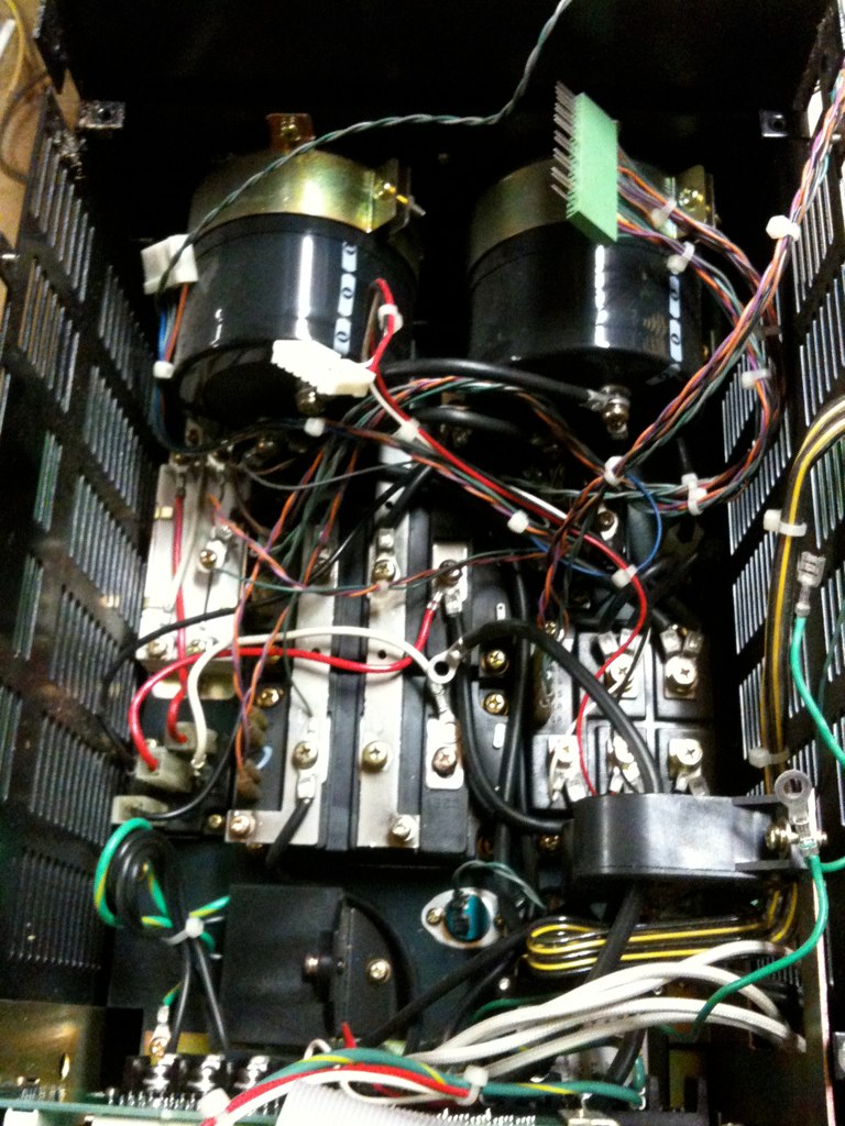
There is 3 QM150DY-H IGBT modules, a 3 phase rectifier, 2 massive ripple caps, a 2 channel hall current sensor, and some other small stuff. All of this is mounted to a heat sink thats about 10" x 10" and 1 inch thick with a fan!!
The IGBT modules are rated to 150A and 600V!! I was thinking of paralleling all 3 with the buss bars that are already on them to create a 600V 450A IGBT. This would allow me to be able to charge my pack at 0.55C or 100A! That is about all the service could handle in a home, I have a friend that I visit at his shop, I would be able to plug into his 3 phase service and easily get 100A 3 phase power.
Here is the diagram for the IGBT:
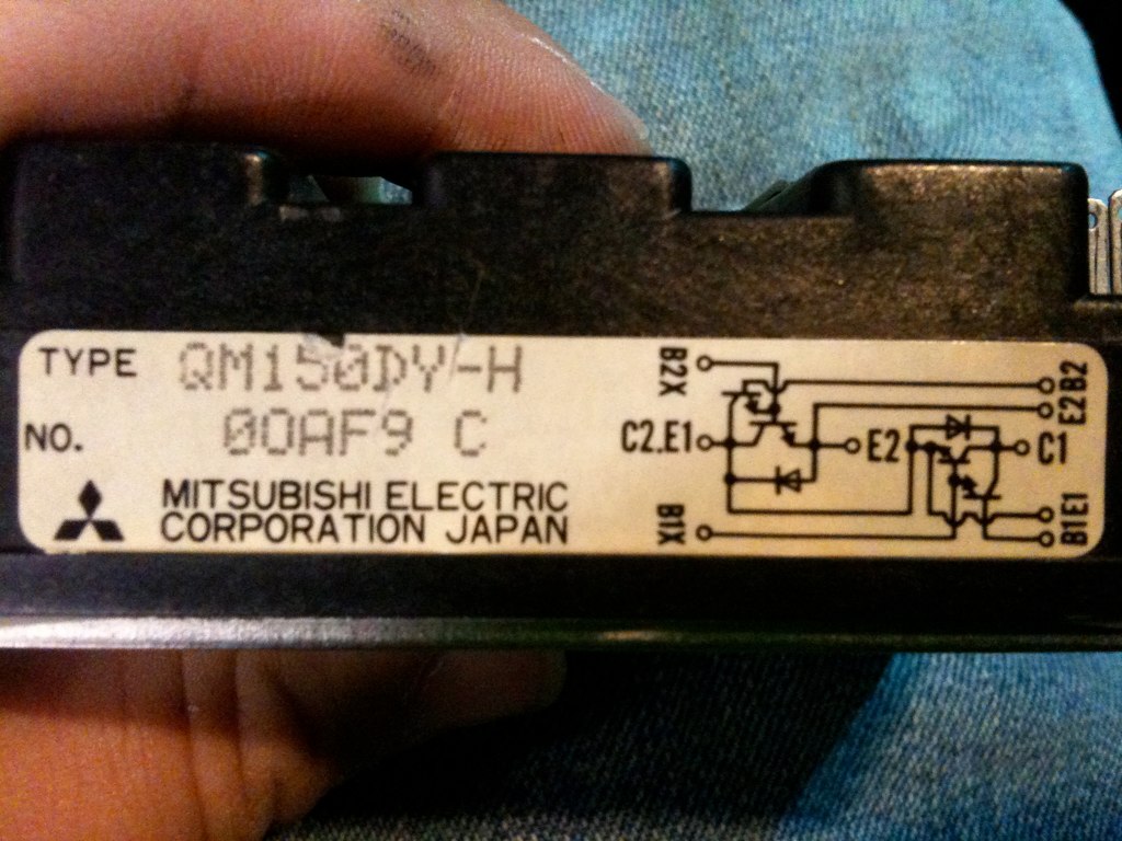
My question is, where do you think is the best place way to hook this up? I was thinking C1 from the B- and C2 to supply ground. B1 or B1X would essentially be the gate.
Do you think these would work?
When will you be releasing the schematic for your design?
Keep up the good work.
-Adam
P.S. Here is the link to the rest of the pictures of the servo pack:
EV Charger - a set on Flickr


 Today
Today


