12-20-2009, 10:37 PM
|
#1 (permalink)
|
|
Master EcoModder
Join Date: Sep 2009
Posts: 5,927
Thanks: 877
Thanked 2,024 Times in 1,304 Posts
|
efficient engine design
By now most people who frequent this forum are familiar with my hydraulic hybrid design, which has recently seen a patent application approval, hopefully with a patent issued sometime in March or April 2010.
It did not start out that way. The IVT in wheel drive (covered in the approved patent application) was an evolution of the original design that was intended as an engine that had some unique characteristics.
The capability to act as its own energy storage system by utilizing the mass of the engine itself as a flywheel to provide short term energy storage and allow the fuel consuming burn cycle to be at highest BSFC while any excess energy was stored in increased speed (RPM) of the mass of the engine to be used during the non fuel consuming "glide" portion of power application.
Consider a flywheel of 200 pounds mass spinning at 4k RPM with a continuously variable transmission that would allow consistent power application as the stored energy of the flywheel was applied to the wheels in a car.
When a predetermined lower RPM threshold was reached the engine would be switched (by changing the stroke from the (0=flywheel) position to a stroke position that would create compression and displacement with fuel consumed and power created.
The created power would be applied to the vehicle power train, while any excess power would result in increased RPM of the "engine" until the upper threshold of RPM was reached, when the stroke would go back to "0" and the engine would again become a flywheel.
The system requires a continuously variable or an infinitely variable transmission to make the transition from "engine" mode to "flywheel" mode imperceptible to the vehicle operator.
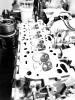
The model illustrated at the bottom of this post is a good representation of the design. It would be 2 cycle and have no valve train, no connecting rods, and no reciprocating parts. It's kind of a combination of the best aspects of piston in cylinder engines and turbines. Pressure from combustion acts directly on the outer rim of the housing. It is a low speed super high torque design.
Through the single intake port comes all the air for combustion and a single injector does all the work. All exhaust gasses exit through another single port and a heat exchanger transfers a significant amount of exhaust heat energy to the incoming air. Ultra high injection pressures would give excellent atomization and low pressure supercharging would be utilized to control cylinder scavenging with a significant amount of natural EGR to minimize NOX production under ultra lean burn conditions.
Variable displacement would allow compression ratios as high as 50 to 1 for diesel applications, and timing of ignition of fuel and air would be controlled through changes in compression ratio, by adjusting stroke distances while the engine was running.
Lubrication and cooling would be through a "dry sump" system where the lubrication fluid was allowed to accumulate in the "crankcase" and be recirculated to a collection sump outside of the engine itself. Thermostatically actuated additional cooling of the lubricating fluid would occur when sustained demands for power required additional cooling of the lubricating fluid. No other cooling system would be necessary.
There would be no induction system throttle control of any kind. Idling would be unnecessary. All the incoming air would need would be a filter and an induction tube, surrounded by the exhaust heat exchanger.
The sole purpose of the engine would be to create energy to be stored in the flywheel. Accelerator pedal inputs would be to the transmission, changing the effective "gear" ratios to increase or decrease the rate of acceleration. Engine on-off operation would be independent of any accelerator pedal position.
This concept dates back to 2003 and 42 pages of original drawings.
The basis of the concept was to allow "pulse and glide" of the engine while maintaining a constant vehicle speed.
Elimination of any idling.
Regeneration of any deceleration forces.
Coasting without engine engagement.
All of this without the necessity for separate systems to store and recover energy. The engine itself was the storage and recovery system.
regards
Mech
The attached photos show the 0 stroke and stroked positions.
|
|
|

|
 Today Today
|
|
|
|
 Other popular topics in this forum...
|
|
|
|
|
12-21-2009, 08:56 AM
|
#2 (permalink)
|
|
needs more cowbell
Join Date: Feb 2008
Location: ÿ
Posts: 5,038
Thanks: 158
Thanked 269 Times in 212 Posts
|
Thanks for sharing, it is curious, could be made to turn probably, lots of details remain though. Just general observations here, I'm sure you are aware. If I understand it right, it looks like where the pistons meet is a busy place.
That bearing has to function as both crank and piston port. So it is hollow with intake and exhaust portings, yet strong enough to be a crank pin, and be articulated (which will change the port timing slightly) .
Also note that model will be out of balance when in engine mode.
The cooling fins on the model are not part of the final design I assume.
How efficient is a CVT for a high torque flywheel?
__________________
WINDMILLS DO NOT WORK THAT WAY!!!
|
|
|
|
|
12-21-2009, 09:06 AM
|
#3 (permalink)
|
|
Administrator
Join Date: Dec 2007
Location: Germantown, WI
Posts: 11,203
Thanks: 2,501
Thanked 2,589 Times in 1,555 Posts
|
Quote:
Originally Posted by Old Mechanic

By now most people who frequent this forum are familiar with my hydraulic hybrid design...
|
I must have missed that thread. Do you have a link to some info on it? |
|
|
|
|
12-21-2009, 09:29 AM
|
#4 (permalink)
|
|
Master EcoModder
Join Date: Sep 2009
Posts: 5,927
Thanks: 877
Thanked 2,024 Times in 1,304 Posts
|
http://ecomodder.com/forum/showthrea...ted-10330.html
dcb;
here is a similar design dating back 130 years that was reported to be almost vibration free at 600 RPM
Check out the Arthur Rigg Water Engine:
Water Engines: Page 3
Of course assuming your belief in the imbalance is correct then the whole mass of the engine serves to control that imbalance in much the same way a flywheel does on other IC engines. There is no reciprocation in this engine (much like a rotary vane pump used in high speed air tools), which is a major factor in balance issues. In the same way a car wheel is imbalanced, the closer the difference in mass is to the center axis of rotation the less effect the imbalance will have.
With the pistons centrifugal force concentrated on the locating pin at the perimeter of the housing, I believe that the balance issues would be minimal.
The WW1 rotary aircraft engines were supposed to be virtually vibration free in operation.
Animated Engines, Gnome Rotary
This technology is ancient as you can see, going back over 100 years. There was supposed to be an Australian who flew a compressed air airplane many years before the Wrights.
I decided to abandon the patent on the engine design and pursue the IVT hydraulic configuration, because the Patent Office refused to acknowledge "novelty" in the design.
The central journal would be about 4 inches in diameter, while the support hub of the rotating block would be 10-12 inches in diameter. Bearings available in those diameters are rated for weights of 40,000 pounds per axle, so I don't think structural integrity is an issue, and research by Virginia Tech with stress analysis actually found the stress issues to be very minor in the hydraulic pump configuration.
The whole idea is based on a low speed, super high torque operation. To accomplish a 60-0 and back to 60 acceleration in a car would only require a change of 1800 RPM in the flywheel mode without any fuel consumption other than that necessary to cover the small percentage of losses.
regards
Mech
|
|
|
|
|
12-21-2009, 09:50 AM
|
#5 (permalink)
|
|
needs more cowbell
Join Date: Feb 2008
Location: ÿ
Posts: 5,038
Thanks: 158
Thanked 269 Times in 212 Posts
|
ok, got it on the balance part,
any comments on the other observations?
__________________
WINDMILLS DO NOT WORK THAT WAY!!!
|
|
|
|
|
12-22-2009, 07:53 AM
|
#6 (permalink)
|
|
Master EcoModder
Join Date: Sep 2009
Posts: 5,927
Thanks: 877
Thanked 2,024 Times in 1,304 Posts
|
The model is a 73 Datsun fan clutch, so the cooling fins are there because it was something that was available and easy to make into the model.
Port timing does change as stroke position is increased, but the TDC point movement is relatively small in relation to port alignment. This could be corrected (if it was needed) with an articulated collar over the hub to maintain port alignment. It is also a function of the length of the journal arm, with a longer arm creating less change. It may be that we will find that the change could actually provide a benefit in dynamic operation.
Just noticing that (dcb) means you have spent some time looking at the design, and I thank you for the effort. The engineering students at Tech told me it was very difficult to understand without the model to demonstrate the principle.
The Basic concept is to address the issues of reciprocation and connecting rod side loads that are a part of any conventional reciprocating engine.
Also to allow the mass of the engine itself to serve as short term storage of energy created when running at BSFC, above any beyond the amount of power required to maintain vehicle speed.
Simplicity is also a benefit. No valve train and a single port for all induction and exhaust functions. Supercharging would allow relatively small intake passageways and high turbulence. Warm up time would be very minimal, with all intake and exhaust passing through the same passageway, you only need a single spark plug and injector (assuming spark ignition-I prefer compression ignition).
Constant load operation without restrictive throttle control would make HCCI operation potentially less difficult to utilize if spark ignition was used as well.
The CVT transmission was my original configuration when I conceived this design over 5 years ago. Now I would use the engine to charge an accumulator for my IVT power train design (see the hydraulic hybrid link). The system requires step less "gear" changes so the energy stored in the flywheel mode can be applied at a constant power level at any flywheel speed within the limitations of the available CVT ratios.
Think of this as a low speed super high torque mechanical capacitor, that can store energy in its own mass, in addition to having an accumulator for additional storage.
http://video.aol.co.uk/video-detail/...ing/2480741041
Notice how long it keeps spinning after the kill the ignition at the end, even with a prop!
Just found this video. Notice the fuel control, or lack of control, the ignition is cut off to stop the engine.
In 1913 a rotary engine was made that produced 160 HP out of 700 cubic inches at 1300RPM. In that same year a Mercedes grand prix engine produced 200 HP at 2200 rpm but it was twice that displacement, and almost 1000 RPM greater speed.
If they could do that in 1913 imagine what could be done today with modern control and construction technology.
regards
Mech
Last edited by user removed; 12-22-2009 at 08:05 AM..
|
|
|
|
|
12-22-2009, 03:45 PM
|
#7 (permalink)
|
|
In Lean Burn Mode
Join Date: Apr 2009
Location: Pacific NW
Posts: 1,561
Thanks: 1,336
Thanked 613 Times in 400 Posts
|
Man I'm still trying to grasp how this thing works??? I feel like a fool.LOL
Is there cylinders and pistons that aren't part of the models that you have shown us???
I'm really trying to understand but I just don't get it 
__________________
Pressure Gradient Force
The Positive Side of the Number Line

|
|
|
|
|
12-23-2009, 11:41 AM
|
#8 (permalink)
|
|
needs more cowbell
Join Date: Feb 2008
Location: ÿ
Posts: 5,038
Thanks: 158
Thanked 269 Times in 212 Posts
|
the model probably isn't to scale, but if I understand it:
the red things are the cylinders
the silver things inside the red things are connecting rods/pistons
the combustion chambers are in the middle
it is a two stroke, so each piston fires once per rev
the lever in the middle provides offset/variable displacement
when the lever is centered the engine is not firing, but is able to act as a flywheel alone.
the porting is like piston porting in a "normal" two stroke, except it has to happen on that center bearing that connects the cylinders, and through the pivot arm and bearing, somehow.
only the outside part rotates (and the pistons/cylinders), the inside hub is stationary
The main question IMHO is after overcoming the technical challenges remaining, will it weigh less than an optimized engine of the same base fuel consumption with an external energy recovery system, like in F1 Regenerative brake - Wikipedia, the free encyclopedia or a standard issue hybrid. packaging size is also a concern though secondary.
__________________
WINDMILLS DO NOT WORK THAT WAY!!!
|
|
|
|
|
12-23-2009, 01:53 PM
|
#9 (permalink)
|
|
Master EcoModder
Join Date: Sep 2009
Posts: 5,927
Thanks: 877
Thanked 2,024 Times in 1,304 Posts
|
The engine would weigh about 200 pounds total for a compact car (2200 pounds), and it would be positioned within the front cross member that locates the suspension. Like it was enclosed in a very strong "cake pan" that served as the structural component of the front suspension, where the suspension parts were anchored.
This provides a scatter shield in case of a catastrophic failure. The bottom of the cross member would be bolted on to provide access for removal.
In less than 1 hour it could removed and totally disassembled, from the bottom, without having to take anything else apart.
The weight of the engine would be determined by the amount of energy you wanted to store and the weight of the vehicle itself. With no cylinder head, or induction system, a single injector, and no valve train, or cooling system other than the lubrication system with thermostatically controlled cooling for the lubricating oil.
If increased weight was desired (for more energy storage) it could be done by simply adding bands of steel to the outside perimeter of the rotating portion of the engine "block" since the greatest mass at the perimeter is the most efficient flywheel. Not a high speed flywheel, max combustion RPM would be about 4000, max regenerate (no fuel consumption) would be 6-7000 RPM.
In the INNAS (previously linked design) the engine only operated 12% ( fuel consuming stroked mode) of the time, so cooling requirements would be minimal. The bypass for the recycled lubricant-coolant fluid would be used to provide passenger compartment heat in cold weather.
The rest of the power train would be CVT and conventional differential to the front wheels, unless you used the IVT power train design. Then the engine would drive a pump which would charge an accumulator with individual IVT units located in each wheel, replacing the conventional brakes on an equal weight exchange.
Accumulator sizes would vary depending on total vehicle weight, probably about 5 gallons for a small car and 10-20 gallons as the cars weight progressed beyond 3000 pounds. Accumulator storage would be sufficient for one 0-70 rapid acceleration event with no help from the engine. Horsepower seconds of storage would range from 500 to 1500 depending on vehicle weight.
On sustained climbs of significant distance where accumulator or flywheel storage was depleted the engine could bypass the accumulator and drive the vehicle directly.
regards
Mech
|
|
|
|
|
12-23-2009, 01:57 PM
|
#10 (permalink)
|
|
Master EcoModder
Join Date: Sep 2009
Posts: 5,927
Thanks: 877
Thanked 2,024 Times in 1,304 Posts
|
It doesn't necessarily have to be 2 stroke, could be configured as a 4 stroke.
I prefer 2 stroke as long as you understand there is no oil mixed with the fuel, and the incoming air has no fuel added until it is just outside the combustion chamber, or actually inside the combustion chamber.
This would depend on whether you are using very high pressure direct injection, or premixing the fuel and air in the single intake port with a heat exchanger from the exhaust port to preheat the mixture for HCCI operation, which should be much easier to accomplish with specific ranges of RPM and loads, with not WOT enrichment or idling necessary, and no manifold vacuum due to elimination of any throttle plate.
regards
Mech
|
|
|
|
|