 09-10-2018, 02:26 PM
|
#41 (permalink)
|
|
Master EcoModder
Join Date: Jan 2017
Location: Istanbul
Posts: 1,245
Thanks: 65
Thanked 225 Times in 186 Posts
|
Do you dfco? Or eoc?
A simple switch under the gas pedal so it does not activate when truing to accelerate. And if you can get the neutral gear and clutch signals (all binary) you would be good.
|
|
|

|
|
The Following User Says Thank You to teoman For This Useful Post:
|
|
 Today Today
|
|
|
|
 Other popular topics in this forum...
|
|
|
|
 09-10-2018, 02:41 PM
|
#42 (permalink)
|
|
Master EcoModder
Join Date: Jan 2017
Location: Istanbul
Posts: 1,245
Thanks: 65
Thanked 225 Times in 186 Posts
|
You could go next generation of eco moddign and hooku up your arduino to the canbus.
Get allll the data you need.
|
|
|

|
 09-10-2018, 02:42 PM
|
#43 (permalink)
|
|
Administrator
Join Date: Dec 2007
Location: Germantown, WI
Posts: 11,203
Thanks: 2,501
Thanked 2,589 Times in 1,555 Posts
|
I use both DFCO and EOC. I'll need to use DFCO when using 'regen' mode on the alternator or the alternator won't spin.
|
|
|

|
 09-10-2018, 03:18 PM
|
#44 (permalink)
|
|
Human Environmentalist
Join Date: Aug 2010
Location: Oregon
Posts: 12,850
Thanks: 4,334
Thanked 4,490 Times in 3,453 Posts
|
Simplest design would be a relay that connects your alternator control wires whenever the brake lights come on. That would mean you would need to lightly press the brake pedal when DFCO. Most elegant design would be to have Arduino monitor for open loop, which usually implies DFCO, and have it control the alternator. You'd also want it to monitor voltage so it activates the alt if the charge level drops too low.
One downside is that open loop is usually activated at full throttle too, so you'd want the logic to check throttle position and not enable the alternator in this situation. Don't want the alternator dragging your acceleration down when mashing the skinny pedal.
|
|
|

|
|
The Following User Says Thank You to redpoint5 For This Useful Post:
|
|
 11-13-2018, 02:11 PM
|
#45 (permalink)
|
|
Administrator
Join Date: Dec 2007
Location: Germantown, WI
Posts: 11,203
Thanks: 2,501
Thanked 2,589 Times in 1,555 Posts
|
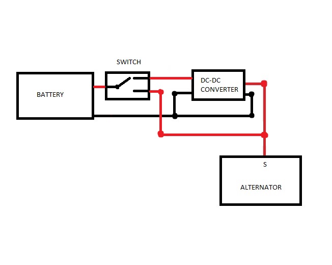
Alright, lets get back to this project. Last I left it, I had fried my dc-dc converter. It can only handle 18V for 100ms, and is really only meant to handle 13.2V which is kind of low. When the alternator kicks on, it boots the voltage up to 14.4V. When you switch back to the dc-dc converter, that is too high and it will eventually fry as mine did. This simply won't work for the next phase of this project. So, we have to revisit the design and make things a bit more robust.
This is what we started with:

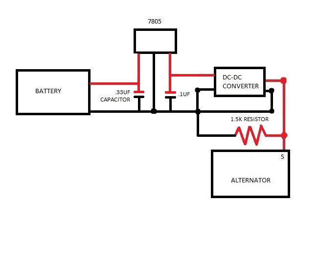
This is what we're now going to. I've added a 7805 linear voltage regulator before the dc-dc converter. This linear voltage regulator will take 7-35V and convert it down to a regulated 5V. So, a voltage spike of 14.4V is nothing for this puppy to handle. It then spits out 5V to the new dc-dc convter which converts 5V to 15V. The old one took 12V and converted to 15V. This design will be a lot more robust and should really never have issues with frying components, yay!
 |
|
|

|
 11-16-2018, 08:57 PM
|
#46 (permalink)
|
|
Administrator
Join Date: Dec 2007
Location: Germantown, WI
Posts: 11,203
Thanks: 2,501
Thanked 2,589 Times in 1,555 Posts
|
I got the new circuit soldered up tonight. Its messy but will work for testing purposes. The two capacitors are normally added when using 7805 chips.
 |
|
|

|
 11-23-2018, 08:51 PM
|
#47 (permalink)
|
|
Administrator
Join Date: Dec 2007
Location: Germantown, WI
Posts: 11,203
Thanks: 2,501
Thanked 2,589 Times in 1,555 Posts
|
Last week I tried out the new circuit. It did not work. Today I got some time to work on it again. I bench tested it and found out that the dc-dc converter was spitting out 24V... The only thing I could think of is that it needs a load to bring it down. So, I added a 1.5k resistor across the output of the dc-dc converter and it dropped the output down to 15.8V. Sounded good enough for my purposes, so I tried it out on the car and it worked great. I finally think I have a stable and reliable circuit to kill the alternator! Yay.
Here is the latest circuit diagram.
 |
|
|

|
 11-23-2018, 10:11 PM
|
#48 (permalink)
|
|
Corporate imperialist
Join Date: Jul 2011
Location: NewMexico (USA)
Posts: 11,275
Thanks: 273
Thanked 3,572 Times in 2,836 Posts
|
I have seen "12v" regulators put out up to 24v under open current conditions.
__________________
1984 chevy suburban, custom made 6.5L diesel turbocharged with a Garrett T76 and Holset HE351VE, 22:1 compression 13psi of intercooled boost.
1989 firebird mostly stock. Aside from the 6-speed manual trans, corvette gen 5 front brakes, 1LE drive shaft, 4th Gen disc brake fbody rear end.
2011 leaf SL, white, portable 240v CHAdeMO, trailer hitch, new batt as of 2014.
|
|
|

|
|
The Following User Says Thank You to oil pan 4 For This Useful Post:
|
|
 11-24-2018, 03:47 PM
|
#49 (permalink)
|
|
Master EcoModder
Join Date: Sep 2012
Location: Victoria, BC
Posts: 1,747
Thanks: 75
Thanked 577 Times in 426 Posts
|
Looks like a lot of work to get it working right...I'll stick to my $0.99 dc-dc converters (regulated, adjustable, up to 28v input) that arrived today. 
Of course, ya never know until you actually hook it up if it's going to work as intended... |
|
|

|
 11-26-2018, 04:03 PM
|
#50 (permalink)
|
|
i should weld
Join Date: Apr 2017
Location: A hilly area in Western Canada
Posts: 30
Thanks: 1
Thanked 1 Time in 1 Post
|
Quote:
Originally Posted by Daox

Just thinking now... if I cut the G wire, the regulator won't have any ground reference unless its grounded to the alternator casing (which is quite possible). So, I wonder if cutting that wire would do it?
|
I think I'd install a manual fan clutch and a voltmeter and declutch it if the battery is sufficiently charged
__________________
2007 Kia Spectra LX, front wheel drive (as all of them), 2 L, 5 speed manual. CEL lit 
|
|
|

|
|