 04-13-2011, 05:36 PM
|
#111 (permalink)
|
|
Master EcoModder
Join Date: Jan 2008
Location: Sanger,Texas,U.S.A.
Posts: 16,534
Thanks: 24,520
Thanked 7,438 Times in 4,818 Posts
|
can you
Quote:
Originally Posted by winkosmosis

Look at the blade... I'm not talking about pitch variation from inside to outside. It's curved from the leading to the trailing edge of the blade. Can you not see that by looking at it?
|
I see the curve.It dates to the 1970s.A close friend got his masters degree in aeronautical engineering working with NASA on airframe integration for these on turbo-prop aircraft.
They are more efficient than other designs.They do provide more thrust for the buck.
They show up on ships and nuclear submarines.
Your premise is correct with respect to efficiency.
|
|
|

|
 Today Today
|
|
|
|
 Other popular topics in this forum...
|
|
|
|
|
04-13-2011, 05:47 PM
|
#112 (permalink)
|
|
Master EcoModder
Join Date: Jan 2008
Location: Sanger,Texas,U.S.A.
Posts: 16,534
Thanks: 24,520
Thanked 7,438 Times in 4,818 Posts
|
shallow
Quote:
Originally Posted by winkosmosis
EXACTLY. That's why a shallow windshield and hood, moving air out of the way (upward) more slowly, are more energy efficient. That's why the Prius has a 20° and a hood with almost the same angle, and all those surfaces are smooth and gradually curved.
|
"On the drag problem of a body,it might be mentioned finally that the shape of a body in front of the largest cross-section has only minor influence on the total drag.The main contributions to the drag force originate from the rear part of the body.It is not important to find a proper shape to divide the oncoming flow but it is very important to design a rear body surface which brings the divided streamlines smoothly together.Optimum shapes are 'streamlined' bodies having a very slender rear part."
Wolf Heinrich Hucho,ph.D. Mechanical Engineering,Aerodynamics Department,Volkswagen AG,aerodynamic consultant. |
|
|
|
|
04-13-2011, 05:50 PM
|
#113 (permalink)
|
|
Master EcoModder
Join Date: Jan 2008
Location: Sanger,Texas,U.S.A.
Posts: 16,534
Thanks: 24,520
Thanked 7,438 Times in 4,818 Posts
|
cowl
Quote:
Originally Posted by winkosmosis
I googled "hood windshield transition".
2009-2011 Dodge Ram pickup trucks
The cowl screen smoothes the airflow transition from hood to windshield, reducing turbulence and wind noise
Car Aerodynamics 101
Vehicles with steep windshields can benefit from a hood fairing to help smooth the transition of air between the hood and windshield.
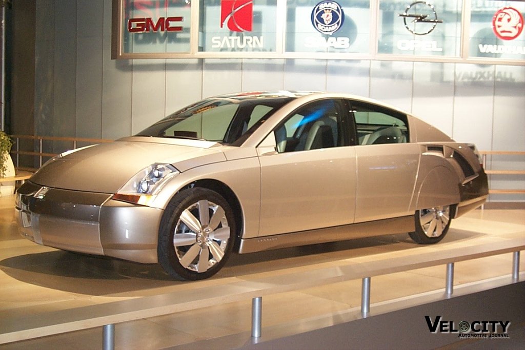
Wait a minute! What's this in front of the GM Precept's windshield?

 |
I tested one at Bonneville in 1990.It made no difference.My data is accurate to 1/1000 of a mph.
|
|
|
|
|
04-13-2011, 06:11 PM
|
#114 (permalink)
|
|
Master EcoModder
Join Date: Jan 2008
Location: Sanger,Texas,U.S.A.
Posts: 16,534
Thanks: 24,520
Thanked 7,438 Times in 4,818 Posts
|
Prius
Quote:
Originally Posted by winkosmosis
What do you mean "no low drag car has a simple inclined windshield"? The Prius has a 20 degree windshield.
Or are you talking about flat vs curved? No one has even mentioned flat windshields.
The more sloped windshield doesn't increase drag.... Those supercars have shallow windshields just like the Prius, because they reduce drag. They aren't building their cars with anti-aero principles. They're designing them to be as aerodynamic as possible, with as little lift as possible, or even downforce. And designing for downforce doesn't mean you suddenly don't care about reducing drag.
Indycars and F1 cars have high coefficients of drag because of their downforce surfaces, but the other surfaces are as aerodynamic as possible. An airplane has a low coefficient of drag when the wings are parallel to airflow, but in the real world they generate lift by flying at an angle, which means their drag is pretty high. Yet airplanes generally have fuselages designed to be as aerodynamic as possible.
By pressurized air I mean air that is at higher pressure than the surrounding atmosphere.
Edit: The article specifically states that you can reduce drag by adding arch and frontal area. This is common sense, like I said in the other thread. If you decrease Cd by 10% and frontal area only goes up by 5%, voila you decreased drag.
|
*None of those cars are low drag*
*Indycar bodies are Cd 0.25
*Indycar bodies with wheels are Cd 0.54
*Indycar bodies with wheels and wings are Cd 1.27
--------------------------------------------------------------------------
* The fuselages which I studied to create the 'Template' are Cd 0.066
--------------------------------------------------------------------------
* Once air begins to move,it cannot be at a higher pressure than the undisturbed air mass around it.
* Air,by definition cannot actually strike the vehicle.Air immediately adjacent to the body boundary is in a zero-slip situation.Air beyond the actual surface will be the turbulent boundary layer.The 'ideal'/'inviscid' outer flow can strike this.
--------------------------------------------------------------------------
Hucho recommends against adding frontal area,however in your example you are correct.A car of Cd 0.30 and frontal area of 22 ft-sq,if modified as in your example would see a 2.75% increase in mpg at 55-mph. |
|
|
|
|
04-13-2011, 06:19 PM
|
#115 (permalink)
|
|
Master EcoModder
Join Date: Jan 2009
Location: Maui, Hawaii
Posts: 813
Thanks: 5
Thanked 34 Times in 26 Posts
|
This thread is turning into walls of text so I want to discuss you arguments one by one
Quote:
Originally Posted by aerohead
* The favorable pressure gradient at the front of the vehicle helps maintain attached flow.It travels along with the vehicle.It has nothing to do with Newtonian physics.It in itself imparts no drag to the vehicle.
* drag is predominantly about pressure differentials.
* Air does not exert a rearward force on the vehicle.
|
Think of a simple example, the wing of a bird. How does a bird fly? By pushing against the air on the downstroke. The air is exerting a force opposite to the direction of motion because it has viscosity and resists movement through it.
How about the propeller? Picture in your mind a simple flat propeller blade. The leading edge slices into the viscous air, and pulls the airplane through the air. Why? Because the air is exerting a force on the blade. That force is both forward (relative to the airplane) and against the motion of the blade. Think of the leading surface of a car as the the leading surface of the propeller.
Similar to the propeller blade is the airplane wing... No, planes don't fly because of Bernoulli's Principle, that's one of those myths that gets repeated even in textbooks.
75% of the lift on a wing comes from the top, and 25% on the bottom according to the FAA. If you were right about no force being applied by air to the leading sloped surfaces of a car, then the bottom of the wing would provide 0% of the lift.
http://www.associatedcontent.com/art...es.html?cat=16
Last edited by winkosmosis; 04-13-2011 at 07:02 PM..
|
|
|
|
|
04-13-2011, 06:25 PM
|
#116 (permalink)
|
|
Master EcoModder
Join Date: Jan 2008
Location: Sanger,Texas,U.S.A.
Posts: 16,534
Thanks: 24,520
Thanked 7,438 Times in 4,818 Posts
|
whole thing
Quote:
Originally Posted by winkosmosis
Read the whole thing. There is a whole section about nose design and separation. They're talking about the hood and windshield angles in the part I was referring to and even showed a diagram of the "bubble".
A flow image doesn't tell you what the vehicle's drag is. Look at the example of the fine looking smoke trails... looks great but doesn't tell you that the Cd of a Ford Escape is 0.4.... And how about the VW Beetle Frank posted? The lines look great, but the Beetle has a Cd of 0.49!
|
*I have many articles and peer-reviewed SAE papers which deal with fore-body aerodynamics.They were important in the 1970s.
If you're looking at Piachna's(sp?) work,his numbers are wrong.
*The Escape,at Cd 0.4 might be considered better than previous sport utilities of double that Cd.
*The Beetle,at Cd 0.495 suffers from its Pseudo-Jaray fast-back body.And remember,this is a 1936 design,when typical cars were Cd 0.70,so it looked pretty good back then.You can fix it by filling in the empty space over the beaver tail.On the modern New Beetle,this will improve the Cd from 0.39,to 0.34.With a 36" 'stinger' she'll drop to Cd 0.29. |
|
|
|
|
04-13-2011, 06:55 PM
|
#117 (permalink)
|
|
Master EcoModder
Join Date: Jan 2008
Location: Sanger,Texas,U.S.A.
Posts: 16,534
Thanks: 24,520
Thanked 7,438 Times in 4,818 Posts
|
bubble
Quote:
Originally Posted by winkosmosis
You'll have to explain that because I don't see how it's possible. 
Air is flowing around the stagnant bubble, applying force to it, and so the bubble itself is high pressure. How can it impart no pressure? You're saying you get something for nothing.
The whole car is surrounded by a boundary layer so does that mean there's no drag? The body of the vehicle is traveling with it. Does that mean the body imparts no force to the uniframe?
Are you familiar with the pitot tube? It's the device that aircraft use to measure airspeed. Airflow increases the pressure inside the tube, the higher the speed the higher the pressure. The air inside the pitot tube is a "bubble" moving along with the plane, and it imparts pressure, otherwise the device wouldn't work. |
* The bubble is higher pressure because it is at rest.It has no dynamic pressure.
* If the ventilation system is closed,the bubble simply travels along as if it were a wart on the body.The onset flow will simply skip over it as if it were solid.
* If the vent is open,a small volume of air from the free stream will travel into the evacuating bubble.
* The bubble imparts no pressure as it is part of the vehicle,just as the air inside your mouth,nose, or ears.It just goes along wherever you go.
* Only the portion of the vehicle with attached flow has a boundary layer against it.The rest will be rolling up into the backflow caused by separation and blended into the turbulence.
* With respect to form drag,the viscous shear during momentum transfer into the boundary layer from the 'inviscid' flow outside is where the surface drag entropy enters the equation.
* The pressure drag,what streamlining deals with doesn't even exist with full streamlining( complete boat-tailing ).Anything short of this and you have separation.The base pressure of the wake is taken at the point of separation.The further back you move the separation,the closer the wake pressure is to the forward stagnation pressure.With the full boat-tail there is no separation,no wake,only skin friction which we can do nothing about.
* I know what a Pitot Tube is.I used to make my living with them.I own only two now.The tube is actually two concentric tubes.The outer tube is cross-drilled to communicate static pressure.The inner communicates ram pressure.The two tubes communicate their pressure either to both sides of a liquid column in a manometer,or to a magnehelic gauge( airspeed indicator).
The 'velocity-pressure' which is indicated can be mathematically converted to reveal air velocity when corrected to local barometric pressure.
* You are correct that the air inside the Pitot tube moves along with the aircraft,as it is a closed system sensor.
|
|
|
|
|
04-13-2011, 07:07 PM
|
#118 (permalink)
|
|
EcoModding New Guy
Join Date: Apr 2011
Location: skyline rd, ca
Posts: 16
Thanks: 0
Thanked 1 Time in 1 Post
|
very interesting - now i need to start experimenting on my car... (evil laugh)
|
|
|
|
|
04-15-2011, 01:31 PM
|
#119 (permalink)
|
|
Master EcoModder
Join Date: Dec 2008
Location: Southern WI
Posts: 829
Thanks: 101
Thanked 563 Times in 191 Posts
|
Quote:
Originally Posted by winkosmosis
According to the diagrams here, the pressure inside the tube is higher than static pressure Pitot Tubes
Look at the equations. They depend on stagnation pressure being higher than static, because you can't take the square root of a negative number
V = \sqrt{\frac{2 (p_t - p_s)}{\rho}}
Pitot tube - Wikipedia, the free encyclopedia
Since the tube is pointing into the airflow, it has to be higher pressure inside than outside. Stick your head out the car window and you can feel the pressure increase in your mouth. Ram air intakes on cars wouldn't work otherwise. |
The stagnation pressure *is* static pressure inside a closed duct with air flow going through it. It always takes more *pressure* either in the form of delta-P or differential to cause air to flow.
I shall mention again that the more accurate pitot tubes have *two* pressure taps.
1) One for static (pressure)
2) One for vacuum (velocity component)
The difference or delta-P between the two tells you exactly the air flow velocity of the air flowing past it.
Jim. |
|
|
|
|
04-15-2011, 03:50 PM
|
#120 (permalink)
|
|
Master EcoModder
Join Date: Jan 2009
Location: Maui, Hawaii
Posts: 813
Thanks: 5
Thanked 34 Times in 26 Posts
|
Quote:
Originally Posted by 3-Wheeler
The stagnation pressure *is* static pressure inside a closed duct with air flow going through it. It always takes more *pressure* either in the form of delta-P or differential to cause air to flow.
I shall mention again that the more accurate pitot tubes have *two* pressure taps.
1) One for static (pressure)
2) One for vacuum (velocity component)
The difference or delta-P between the two tells you exactly the air flow velocity of the air flowing past it.
Jim.
|
That's was my whole point. The inside of the tube that points into airflow is higher pressure than the surrounding air, not lower.
http://en.wikipedia.org/wiki/Pressur...ation_pressure
Stagnation pressure is the pressure a fluid exerts when it is forced to stop moving. Consequently, although a fluid moving at higher speed will have a lower static pressure, it may have a higher stagnation pressure when forced to a standstill. Static pressure and stagnation pressure are related by the Mach number of the fluid. In addition, there can be differences in pressure due to differences in the elevation (height) of the fluid. See Bernoulli's equation (note: Bernoulli's equation only applies for incompressible, inviscid flow).
The pressure of a moving fluid can be measured using a Pitot tube, or one of its variations such as a Kiel probe or Cobra probe, connected to a manometer. Depending on where the inlet holes are located on the probe, it can measure static pressure or stagnation pressures.
|
|
|
|
|


