05-28-2020, 11:02 AM
|
#21 (permalink)
|
|
Cyborg ECU
Join Date: Mar 2011
Location: Coastal Southern California
Posts: 6,302
Thanks: 2,374
Thanked 2,176 Times in 1,471 Posts
|
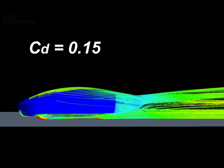
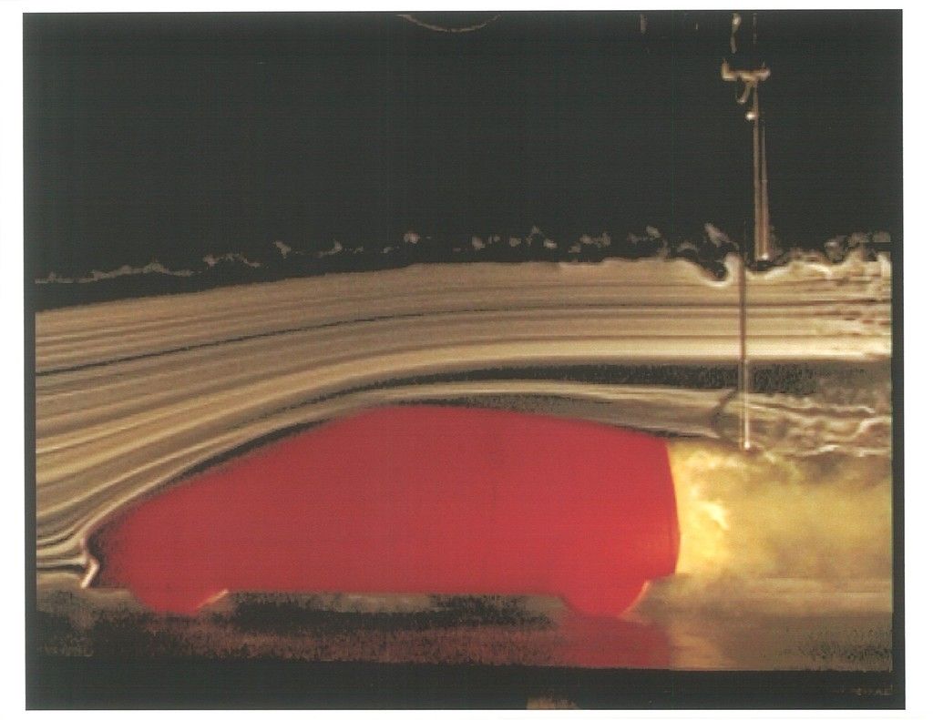
From the EM archive (the wind tunnel, smoke thread)
__________________
See my car's mod & maintenance thread and my electric bicycle's thread for ongoing projects. I will rebuild Black and Green over decades as parts die, until it becomes a different car of roughly the same shape and color. My minimum fuel economy goal is 55 mpg while averaging posted speed limits. I generally top 60 mpg. See also my Honda manual transmission specs thread.


|
|
|

|
|
The Following User Says Thank You to California98Civic For This Useful Post:
|
|
 Today Today
|
|
|
|
 Other popular topics in this forum...
|
|
|
|
|
05-28-2020, 05:20 PM
|
#22 (permalink)
|
|
Banned
Join Date: Nov 2017
Location: Australia
Posts: 2,060
Thanks: 107
Thanked 1,608 Times in 1,137 Posts
|
I don't have that edition (5th edition is on its way - I've been waiting over 2 months) but the 1987 edition I do have covers similar ground.
This diagram, for example, (P201):

Obviously, there isn't just one 'template' shape that is best.
(In this diagram note also how the plan views of the shapes differ considerably.)
Last edited by JulianEdgar; 05-28-2020 at 06:17 PM..
|
|
|
|
|
05-28-2020, 05:24 PM
|
#23 (permalink)
|
|
Banned
Join Date: Nov 2017
Location: Australia
Posts: 2,060
Thanks: 107
Thanked 1,608 Times in 1,137 Posts
|
Quote:
Originally Posted by Piotrsko

Because it would be optimized for the conditions experienced not just a calculated set of non infinite parameters. Or as aerohead calls it rolling floor effects. If you take your calculated profile and then modify it for local conditions, either the ordinates would be copies or very similar depending on how the aspect ratio is dealt with. Otoh, I have seen 1/1 aspect ratio low drag profiles and they are........ odd.
|
I don't understand your point. Taking an aerofoil designed for aircraft flying in ground effect as the starting point for a low drag shape for a car doesn't seem to me to make much sense.
Quote:
Originally Posted by Piotrsko
By the way, look out the window of a commercial airline in flight and notice how lumpy the upper surface is. Definitely not surgical smooth. Ditto for one piece composite or military although those are smoother.
|
That's right, and I'd be very surprised if the design of the practical wing shape doesn't take that surface roughness into account. (As opposed to a simulation of a perfectly smooth aerofoil.) |
|
|
|
|
05-28-2020, 06:57 PM
|
#24 (permalink)
|
|
Banned
Join Date: Nov 2017
Location: Australia
Posts: 2,060
Thanks: 107
Thanked 1,608 Times in 1,137 Posts
|
Quote:
Originally Posted by JulianEdgar
I don't have that edition (5th edition is on its way - I've been waiting over 2 months) but the 1987 edition I do have covers similar ground.
This diagram, for example, (P201):
Obviously, there isn't just one 'template' shape that is best.
(In this diagram note also how the plan views of the shapes differ considerably.) |
Note also how solid line shape (VW blunt body) likely has a large wake and AWA shape likely has very small wake - and yet the two shapes have the same drag.
If you look at the direction and strengths (ie vectors) of the likely lift forces occurring on the two shapes, you can start getting a feel for why this is so.
Lift is very important!
|
|
|
|
|
05-29-2020, 11:59 AM
|
#25 (permalink)
|
|
Master EcoModder
Join Date: Jan 2008
Location: Sanger,Texas,U.S.A.
Posts: 16,470
Thanks: 24,498
Thanked 7,431 Times in 4,814 Posts
|
Cd 0.16
Quote:
Originally Posted by California98Civic
|
Sure could use an overhead, plan-view of this model. It began with Klemperer in 1922. When Buchheim et al. re-investigated it in 1981,as the Volkswagen 'Drop' shape, in plan-view,the car was 100% boat-tailed.Which is lost on the viewer when limited to the side elevation . The car's performance is completely predicated upon the full-boat tail.
__________________
Photobucket album: http://s1271.photobucket.com/albums/jj622/aerohead2/
|
|
|
|
|