Go Back   EcoModder Forum > EcoModding > Fossil Fuel Free
Register Now
 Register Now
 

Reply  Post New Thread
 
Submit Tools LinkBack Thread Tools
Old 03-28-2014, 06:12 PM   #21 (permalink)
Dreamer
 
Join Date: Nov 2013
Location: Australia
Posts: 350
Thanks: 95
Thanked 214 Times in 151 Posts
Quote:
Originally Posted by mechman600 View Post
I tried this with a 2N7000, but I could not make it work for the life of me. It either stayed switched on (no matter what PMW value) or if I switched resistors to different spots (like a 5K from the 2N7000's gate to ground), my test LED switched on when PWM was 1 but the current did not increase as I turned it up.

Something like this maybe?


Last edited by Astro; 03-29-2014 at 01:49 AM.. Reason: Resized image so that resize bar doesn't always show.
  Reply With Quote
The Following User Says Thank You to Astro For This Useful Post:
P-hack (03-28-2014)
Alt Today
Popular topics

Other popular topics in this forum...

   
Old 03-28-2014, 06:18 PM   #22 (permalink)
Master EcoModder
 
P-hack's Avatar
 
Join Date: Oct 2012
Location: USA
Posts: 1,408

awesomer - '04 Toyota prius
Thanks: 102
Thanked 252 Times in 204 Posts
also, the pwm frequency doesn't need to be anymore than visual limits, like 60hz. But 7/8ths is plenty good too
  Reply With Quote
Old 03-31-2014, 10:00 AM   #23 (permalink)
Master EcoModder
 
mechman600's Avatar
 
Join Date: Jul 2008
Location: Langley, BC
Posts: 1,228

Fusion - '16 Ford Fusion Hybrid SE
Thanks: 190
Thanked 275 Times in 168 Posts
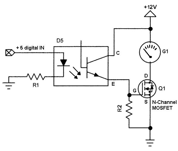
Astro, the schematic you posted above is the exact circuit I attempted and could not make work. I suspect the opto is not very good at outputting a nice square wave, and since the transistor will stay on with the most minuscule voltage on the gate, it simply never turns off. I suppose I could try to slow down the PWM frequency (easy enough to do) but this throws all the delay timers off. And besides, I don't feel like doing it.

The solution I did come up with is simple enough - a 100 ohm bypass resistor between gauge signal and ground. At 0 PWM it sits on the empty line and at 255 PWM it is just short of the full line. Good enough!

Here is the schematic of the whole entire thing:
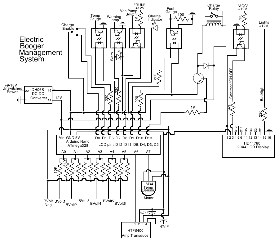

INTERESTING BITS:

Warning Lamp: the ex-low oil pressure warning lamp

Vac Pump Switch/"Run" +12V: monitors the vacuum pump switch when the car is on; if the switch remains closed for more than 10 seconds, the warning lamp is flashed and "VACUUM PUMP FAILURE" is displayed

"ACC" +12V: turns the display on when the keyswitch is turned the first click; I was going to trigger a pin on the Arduino (using lcd.display() and lcd.noDisplay() functions) but I ran out of pins ; opening the display's contrast pin also turns the screen off.

All my bits and pieces have arrived from Digikey. All I am waiting for is my Hong Kong sourced 20X4 LCD display.

Last edited by mechman600; 04-01-2014 at 02:04 AM..
  Reply With Quote
The Following User Says Thank You to mechman600 For This Useful Post:
P-hack (03-31-2014)
Old 04-06-2014, 11:47 AM   #24 (permalink)
Master EcoModder
 
mechman600's Avatar
 
Join Date: Jul 2008
Location: Langley, BC
Posts: 1,228

Fusion - '16 Ford Fusion Hybrid SE
Thanks: 190
Thanked 275 Times in 168 Posts
Quote:
Originally Posted by Daox View Post
I used one of the Haas current sensors that Paul's open revolt uses in my BMS, but it wasn't as accurate as I'd like it to be.
Did you include the capacitors that are in the datasheet? Omitting them would certainly cause erratic readings.

The 47nF cap between 0V and 5V isn't necessary because the arduino already has a much larger cap between its 5V and ground. But the 4.7nF cap between output and 0V will no doubt smooth out signal irregularities.
  Reply With Quote
Old 04-06-2014, 12:08 PM   #25 (permalink)
Master EcoModder
 
P-hack's Avatar
 
Join Date: Oct 2012
Location: USA
Posts: 1,408

awesomer - '04 Toyota prius
Thanks: 102
Thanked 252 Times in 204 Posts
mucking about with resistor values:
Code:
tap   divider   sense  watts   resolution per bit
12v   20k/10k   4v     0.005   0.01171875v
24v   50k/10k   4v     0.010   0.0234375v
36v   80k/10k   4v     0.015   0.03515625v
48v  110k/10k   4v     0.020   0.046875v
60v  140k/10k   4v     0.025   0.05859375v
72v  170k/10k   4v     0.030   0.0703125v

max bit level rounding error @ 72v = +-0.123046875v

Last edited by P-hack; 04-07-2014 at 10:20 AM..
  Reply With Quote
Old 04-07-2014, 09:16 AM   #26 (permalink)
Administrator
 
Daox's Avatar
 
Join Date: Dec 2007
Location: Germantown, WI
Posts: 11,203

CM400E - '81 Honda CM400E
90 day: 51.49 mpg (US)

Daox's Grey Prius - '04 Toyota Prius
Team Toyota
90 day: 49.53 mpg (US)

Daox's Insight - '00 Honda Insight
90 day: 64.33 mpg (US)

Swarthy - '14 Mitsubishi Mirage DE
Mitsubishi
90 day: 56.69 mpg (US)

Daox's Volt - '13 Chevrolet Volt
Thanks: 2,501
Thanked 2,586 Times in 1,554 Posts
Quote:
Originally Posted by mechman600 View Post
Did you include the capacitors that are in the datasheet? Omitting them would certainly cause erratic readings.

The 47nF cap between 0V and 5V isn't necessary because the arduino already has a much larger cap between its 5V and ground. But the 4.7nF cap between output and 0V will no doubt smooth out signal irregularities.
Its been a while so I'm not absolutely sure. I believe I did. In any case, I suggest testing things to make sure they're accurate before you go driving off into the sunset.

You're doing a great job! I look forward to more updates.

__________________
Current project: A better alternator delete
  Reply With Quote
Reply  Post New Thread


Powered by vBulletin® Version 3.8.11
Copyright ©2000 - 2024, vBulletin Solutions Inc.
Content Relevant URLs by vBSEO 3.5.2
All content copyright EcoModder.com