 05-15-2020, 05:59 PM
|
#1 (permalink)
|
|
Banned
Join Date: Nov 2017
Location: Australia
Posts: 2,060
Thanks: 107
Thanked 1,608 Times in 1,137 Posts
|
Measuring stuff
Rather like when air/fuel ratio meters and knock sensing equipment became widely available and so transformed DIY engine tuning, the use of on-road aero measurement means you no longer have to guess - instead you can see for yourself what is happening. And the measurements are all made in an absolutely real world environment.
Wool tufts - see flow behaviour.

Example uses: Find areas of separated and attached flow, ascertain flow directions, see changed flow behaviour caused by modifications.
Equipment: yarn, scissors, tape, camera.
Complexity: easy to do, but interpretation of results requires some knowledge
Comment: still the easiest and best
Cost: $5 (if you have camera)
Coarse pressure measurement - measure large aerodynamic pressures.
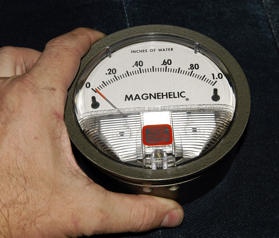
Example uses: find best location of hood vents, measure pressure differentials across heat exchangers.
Equipment: Magnehelic gauge, hose, tape.
Complexity: easy to do and interpretation of results also fairly easy
Comment: good entry into world of aero pressure testing
Cost: $50 (secondhand gauge)
Surface pressure measurement - measure pressures on panels above and below the car, both negative and positive.
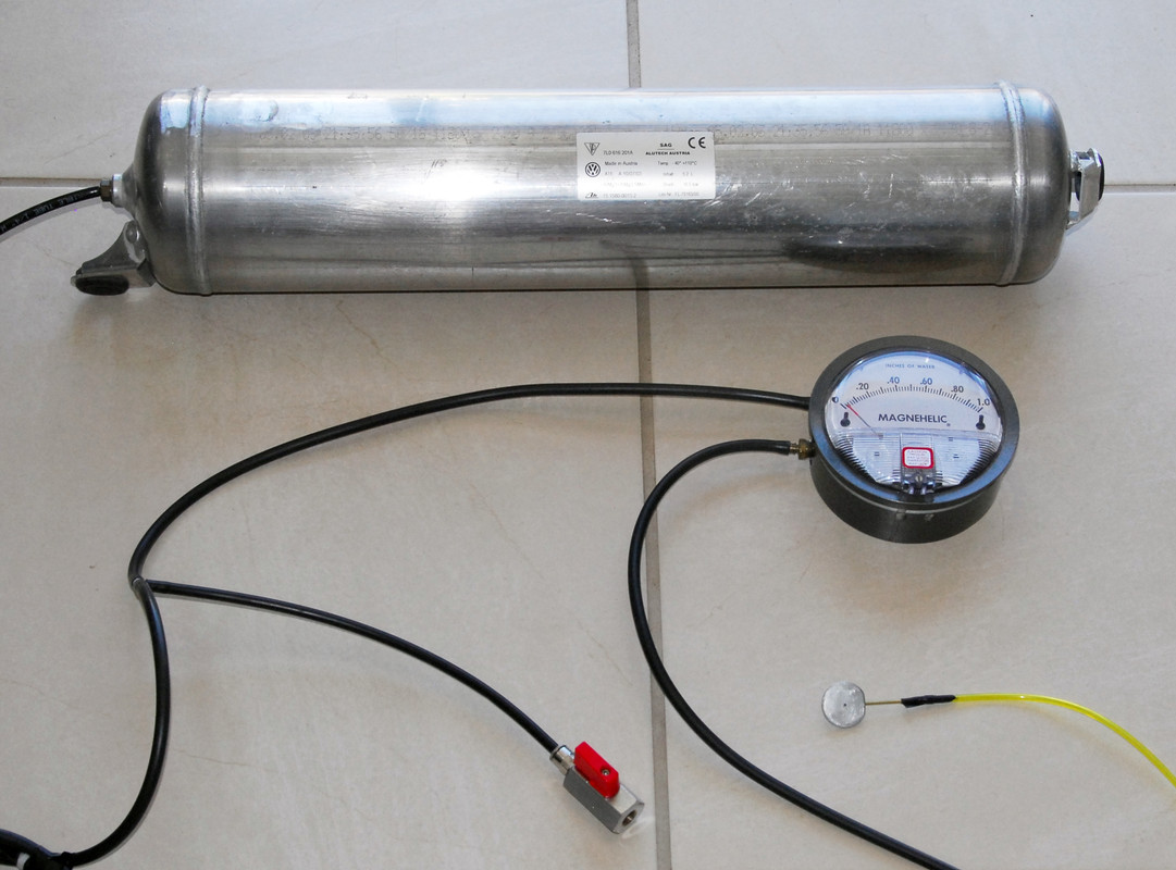
Example uses: directly measure pressures causing lift/downforce, see changed pressures resulting from modifications like spoilers and air dams, measure wake pressures.
Equipment: Magnehelic gauge, surface pressure puck, sealed vessel, ball valve, hose.
Complexity: needs far more care than when doing coarse pressure testing. Interpretation of results fairly easy
Comment: brilliant window into seeing what is actually causing thrust/drag, lift/downforce
Cost: $100-200.
Throttle stop testing - directly measure changes in total drag over about 2 per cent.

Example uses: measure drag change results of modifications
Equipment: digital speed measurement, display of actual throttle blade opening.
Complexity: needs care in testing procedure, interpretation of results easy
Comment: much better than coastdown testing but probably won't work on cars with CVT or electronic throttles
Cost: depends on what needs to be purchased - $0 - 100
Lift / downforce measurement - directly measure amount of lift or downforce
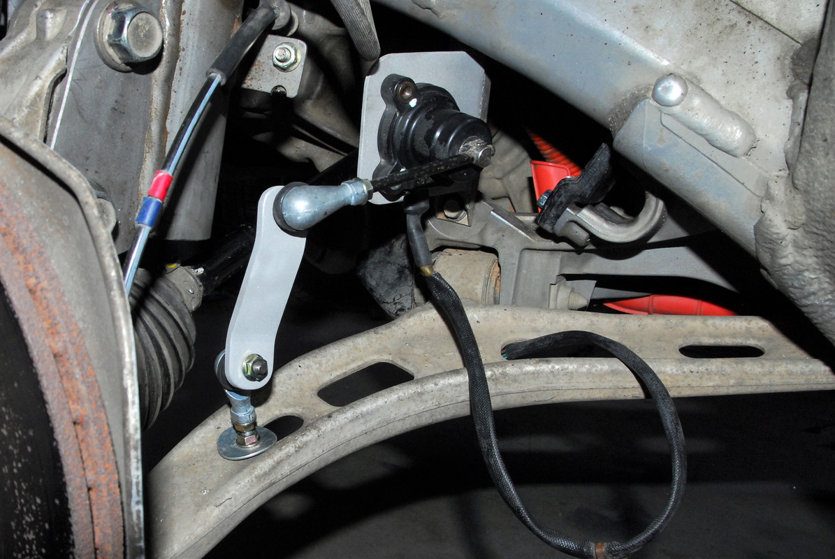
Example uses: see how much lift is occurring, measure effectiveness of modifications, calculate coefficient of lift (front, rear)
Equipment: ride height sensors (eg from an air suspension car), regulated 5V supply, electronic means of averaging output value
Complexity: fitting sensors can be tricky, some basic knowledge of electronics needed, results easy to interpret
Comment: once installed, can be accessed whenever data is needed. Accuracy will diminish with very stiff suspension cars.
Cost: $50-100
Eroding clay technique - see fine details of airflow

Example use: see attached / separated flow
Equipment: fine clay (eg fire clay), water spray bottle
Complexity: needs patience and care in application and testing, analysing results requires some knowledge
Comment: allows you to see very tiny details of flow
Cost: $20
Last edited by JulianEdgar; 05-15-2020 at 10:20 PM..
|
|
|

|
|
The Following 5 Users Say Thank You to JulianEdgar For This Useful Post:
|
|
 Today Today
|
|
|
|
 Other popular topics in this forum...
|
|
|
|
 05-15-2020, 11:06 PM
|
#2 (permalink)
|
|
Banned
Join Date: Nov 2017
Location: Australia
Posts: 2,060
Thanks: 107
Thanked 1,608 Times in 1,137 Posts
|
For me, the huge advantage of testing is that you can see what really happens, not what some people suggest might happen.
Testing can be quite salutary. When I first installed my GOE222 profile rear wing, I set it by eye at what I thought would be a good starting point angle of attack. But the wing did nothing - it produced no measurable downforce (or less lift).
I then did about ten tests using different attack angles, and found that the angle that gave best downforce 'looked' all wrong. What I hadn't considered was that the airflow coming down the rear hatch of the Insight was not parallel to the ground, so setting the wing angle according to the official lift/drag curves for the GOE222 profile gave poor results. Instead, it had to be set to provide that angle of attack to the true oncoming airflow direction. Obvious when you think about it - but I hadn't thought of it.
When I measured surface pressures on the XE Jaguar, I found that my results matched pretty well with Jaguar's CFD, except that I could not measure positive pressure at the base of the rear glass, as their CFD showed. I was in communication with Jaguar's chief aerodynamcist and we had an interesting conversation about the discrepancy. In short, he said it could be either the CFD in error, or my measuring in error. I was interested that he nominated both. (And he wasn't just being polite. He was certainly not backward in suggesting if I had written something wrong.)
When I first started using the Magnehelic gauge to measure pressures, about 16 years ago, I was trying to improve airflow through an under-hood intercooler. I was successful in improving its performance, but what I most remember is watching the gauge and seeing a further thing that influenced the actual pressure differential across the intercooler core - turbulent atmospheric airflow. When I was in the wake of another car, I could see the gauge flickering. And when I passed through small hills and valleys you could see the pressure differential across the intercooler change a lot in the gusty crosswinds.
In the same way, if you are measuring the pressure differential between the top-of-hood and under-hood (eg to best site vents), you can see major changes in the pressure differential with yaw (ie crosswinds). I always wondered that older Japanese cars used to place vents down each side of the hood (and so not in the area that normally has greatest pressure differential, which is towards the front of the car). But then when I did the measurements, I found that those side locations worked far better than you'd first expect because of the yaw component of the airflow that occurs in crosswinds.
However, by far the most exciting measurement technique I have used has been measuring suspension height - and so lift/downforce. It was a bit serendipitous - I had installed air suspension on my car, so needed front and rear height sensors. With the suspension installed and working, I wanted to monitor height, so fed the data into my MoTeC dash so I could watch it 'live' (Developing the control system for the air suspension took about a year and went through three major iterations.) Then it occurred to me - why not use this data to assess lift/downforce? With that incentive, I decided to develop proper front and rear undertrays with a rear upward section (ie diffuser). It also gave me an added impetus to research diffuser angles, that I was already doing for the book.
The first test drive at 100 km/h with the undertrays fitted caused my dash warning to flash - RIDE HEIGHT LOW! (I had programmed the dash to give warnings like this, in case the suspension control system went mad or leaked, etc.) The change in ride height caused by the downforce was enough to trigger that warning (I think I had it set for a ride height 10mm lower than normal.) So the undertrays were working, not only in reducing lift but in developing real downforce. But could I feel it - or was it one of those things that's undetectable? It was (and remains) quite obvious, and when I measured how many kg it is, that's not surprising. It's an uncanny feeling - the tyres pushing down harder on the road (and so having more grip) but without the car having any more mass. It also makes an obvious difference to straightline stability. I had both undertrays off about 12 months ago and the car was noticeably worse in stability and cornering.
I recently measured pressures under the Insight's front and rear undertrays at a single speed (70 km/h - you don't need to be going fast) to see if they improved (ie got lower) as ride height decreased. What I found was that going lower than 130mm (rear clearance) and 110mm (front clearance) gave no advantage - but at ride heights above those figures, downforce decreased rapidly. This is a perfect example of measuring what is really happening, not what people think might be happening, or what happened in textbook or tech paper references to other cars. Just measure your own.
My Edgarwits (aerofoil-based external air curtains) have measurably reduced drag. But I think that they've also done something to the undercar airflow. (The wool tuft testing showed the side airflow pattern altered, and it appeared the airflow from the car's side to the undercar was changed.) So what have they done to lift/downforce? I am not sure, but one day I'll spend 30 minutes and do some testing measuring undercar pressures with the Edgarwits on and off. Then I will know.
No theory, no guesswork, no opinion, no speculation - just what is really happening.
|
|
|

|
|
The Following 4 Users Say Thank You to JulianEdgar For This Useful Post:
|
|
 05-16-2020, 03:23 AM
|
#3 (permalink)
|
|
Banned
Join Date: Nov 2017
Location: Australia
Posts: 2,060
Thanks: 107
Thanked 1,608 Times in 1,137 Posts
|
In all on-road testing (other than long-term mileage) it's very important that you're absolutely rigorous in the testing.
For example, in my throttle stop testing I:
- Use the same section of straight road each time
- Pass a marker at the entrance to the straight at exactly the same speed with exactly the same run-up distance each time
- Hold a constant throttle position
- Measure the maximum speed at the same point each time
- Repeat the run
I then make a quick aerodynamic change (eg to the angle of the Edgarwit) and repeat the above process.
Before I drive to my test location, I make a list of the tests I am going to do, and draw up a table so the results can be easily written-in as each test is done. That lists of tests includes returning the car to its standard form several times during the test session. Obviously all of those 'standard form' tests should give the same results. With throttle stop testing, I usually also do a windows up / windows down comparison and check these results match what I've previously recorded on days of the same weather.
It's quite easy to lose concentration when doing dozens of tests. To avoid that, I say out aloud in the car what I need to do just as each run starts. So I might say, "Fifth gear, 100 kays entrance, top-right speed." Or, "Reset pressure chamber, 80 kays, 4th gear, early reading."
When trying new modifications, I have also found it much more preferable to make major changes. So if trialling an undertray, trial a big one. If trialling a rear spoiler, trial a big one. These mock-ups don't need to be anything special - cardboard, plywood, corfboard, tape.
What you are looking for is a major, measurable change. Things might be worse, or things might be better - but they need to have measurably changed.
Once it's established that you are measuring the change you've made, then you can finesse the modification from that point. The alternative (making tiny changes) is that you may end up chasing testing scatter (ie normal variations in tests) rather than the results of your modification. This can be very confusing and waste a lot of time.
I've found it's really easy in testing to let your hopes and desires over-ride good testing approaches. To avoid this, I deliberately don't try to memorise results as I am doing tests - I complete the series of tests and only then look at the results more closely.
It's also really important that, once you've established you are measuring real changes, you believe your tests. I've lost count of the number of times I have done a series of tests and disbelieved the results - only to find through further testing that the original tests were correct. Here's also where so much of the theory and judgements that you read on discussion groups (including this one) can lead you astray. What works on one car may well not work on another, and vice versa. The tech literature is full of examples where the results of the same approach differs from car to car, and when you are testing your own car, you'll soon find that out for yourself. And that's especially the case with pressure testing (both coarse and panel measurement).
For example, in that original underhood intercooler development, where I was improving flow across the intercooler core, my first test found that the air was coming in through the front grille, going through the radiator, passing up through the intercooler, and then flowing out through the forward-facing scoop! I am quite certain that wouldn't have been the judgement of any discussion group...
Finally, I am not wedded to the idea that each of my modifications will work. So, when I test them and I don't think the results are satisfactory, I don't try to rationalise the outcome. I don't say, "The test results were nothing special but I am sure the modification is working." Instead I say, "Damn, it didn't work. Oh well." The likelihood that you will become wedded to a mod is highest when you spend the most time and energy on making it. Therefore, always initially trial the quickest and simplest mock-up you can make. Overall, it saves far more time by making (maybe) three iterations of a successful modification, rather than making an elaborate first version of every modification - including those that turn out not to work. |
|
|

|
|
The Following 3 Users Say Thank You to JulianEdgar For This Useful Post:
|
|
 05-16-2020, 06:03 PM
|
#4 (permalink)
|
|
Banned
Join Date: Nov 2017
Location: Australia
Posts: 2,060
Thanks: 107
Thanked 1,608 Times in 1,137 Posts
|
I have been testing my car modifications on the road since the mid 1980s. That included the basics like stopwatch testing - but basics most people seldom then seemed to do.
I remember, in about 1988, testing the performance 'gain' of the expensive new exhaust I'd just had fitted to my turbo 3-litre - only to find that against the stopwatch, there was no measurable performance improvement at all. That was about the time I decided following the prevailing wisdom ("Fit a two-and-a-half-inch exhaust to the Commodore and there'll be a real performance gain") was best ignored.
My next car, a Subaru Liberty RS (Legacy in most parts of the world - the predecessor to the WRX) I decided to modify very carefully. An incentive was that I was now also writing freelance articles for modified car magazines, and so if I could show people some good techniques, the articles were more likely to be bought. (I ended up selling 1000+ articles in Australia, the UK and the US.)
I decided to modify the intake system of the Subaru. I was talking to an experienced race engine builder (he had his own engine dyno, etc) and he made a throwaway line that fascinated me. He said, "Just put a vacuum gauge on the intake before the throttle and that will show you the intake restriction".
I don't think he'd ever actually done it, because I found that a normal vacuum gauge had no-where near the sensitivity. But I think he'd watched intake ducting being pulled closed at full load on his engine dyno, and made the deduction. So I investigated what instruments that could be used to measure very small pressures, and discovered manometers. I then built a simple vertical tube water manometer and found that it was brilliant.
By connecting the manometer to the intake at different positions, and then driving the car at full load on the road, you could directly measure the flow restrictions of each part of the intake system. Even better, once you'd found a specific restriction, you could then modify just that part of the intake and then measure the difference - all at full engine airflow. (So, vastly better than testing the intake on a flowbench.)
For example, say the outlet of the airbox was measured as being restrictive. You could then increase the outlet pipe size, or add a better bellmouth, and directly measure the improvement - eg a pressure drop here of 4 inches of water dropping to 2 inches of water. By finessing the intake, typically at almost no cost and using just basic hand tools, I found it wasn't hard to drop the flow restriction of the Subaru by over 60 percent. The acceleration improvement was immediately measurable against the stopwatch on the road. (Incidentally, I have also always recorded a fuel economy improvement with better flowing intakes.)
But the water manometer was a bit messy, and I found out about Magnehelic gauges. By using a Magnehelic gauge, I could measure intake restriction without needing a passenger to hold and observe a water manometer. And since the Magnehelic gauge had two ports (ie pressure and vacuum), I realised I should technically be able to measure positive pressures in the intake - but only if I sited it in an area of high aerodynamic pressure. To my astonishment, the readings worked - with the intake moved to the right place, positive pressure was measurable in the intake prior to the filter box.
I've since used the Magnehelic measuring technique to modify the intake systems on many of my cars.
To me, current DIY aerodynamics modification has many parallels with my pressure measuring technique for modifying intakes. To decide which modifications will work, you can guess, using generic rules of thumb or look at what others do. But it's all hit and miss, and because so many of the modifications don't do anything positive, costs a lot in terms of the outcomes that are actually achieved.
To be honest, it is also an approach that I just can't understand. Why would people often rather waste money, time and effort than do some simple testing to find out what works?
But after all, decades after I first wrote about the pressure drop testing of intake systems - articles that were and remain very popular - most people still use rules of thumb for improving intake systems. Unfortunately, my testing suggests that a significant number of those rules of thumb are wrong.
Last edited by JulianEdgar; 05-16-2020 at 06:11 PM..
|
|
|

|
|
The Following 4 Users Say Thank You to JulianEdgar For This Useful Post:
|
|
 05-16-2020, 09:49 PM
|
#5 (permalink)
|
|
Rat Racer
Join Date: May 2011
Location: Route 16
Posts: 4,150
Thanks: 1,784
Thanked 1,922 Times in 1,246 Posts
|
Rules of thumb are there because they were once accurate. Lots of them just didn't get changed as circumstances changed. Your work can change some of them for the better. Thanks for putting it up here.
__________________

Quote:
Originally Posted by sheepdog44

Transmission type Efficiency
Manual neutral engine off.100% @∞MPG <----- Fun Fact.
Manual 1:1 gear ratio .......98%
CVT belt ............................88%
Automatic .........................86%
|
|
|
|

|
|
The Following User Says Thank You to Fat Charlie For This Useful Post:
|
|
 05-17-2020, 02:39 AM
|
#6 (permalink)
|
|
Banned
Join Date: Nov 2017
Location: Australia
Posts: 2,060
Thanks: 107
Thanked 1,608 Times in 1,137 Posts
|
So before you can test the modifications you have made, you need to decide what modifications to make, and how to make them.
So that I don't get people's noses out of joint (because whatever aero mod I pick, they'll think it's criticism directed at them), let me give an example from a different area of car modification.
When I decided to turbo my Gen 1 Honda Insight, I first looked at what others had done. There were then only a handful of Gen 1 Insights that had been turbo'd (there probably still are), and there were photos around of all the installations.
I remember one in particular, because as I looked at it, it became my role model in how not to do it. Nearly every single aspect that I could see was poorly done, expect for one. (That one was the turbo choice, that looked fine.)
It was intercooled, but the intercooler was behind the radiator. The intake to the turbo was picking up hot air - definitely not good on a turbo car - and the engine management mod was, even then, decades out of date. (It used an extra injector.) It had also, not surprisingly, experienced an engine failure through a melted piston. (Oddly, this rather important fact was almost always brushed under the carpet.)
Now the person who had done the mods must have done them that way for a reason - and as far as I could see, it was because those ways were easy. So why hadn't he mounted the intercooler in front of the radiator? As I looked at my car in more and more detail, it became obvious that it was darn near impossible to fit an intercooler in front of the radiator - and also get the plumbing to and from it. So I needed to go water/air for my intercooling. (It's much easier to run small diameter hoses to a front extra radiator.)
Using an extra injector is a really poor way of doing things, so I needed bigger injectors. Now, what injectors fitted? Someone on the same discussion group described some Toyota ones that dropped straight in - and their sizing looked fine to my eyes, so I took that information and used it. (And it proved to be good information.)
To make the piping runs neat, and not pick up hot engine bay air, a new airbox would be needed. I looked and looked for a replacement from another car, but in the end gave up and made my own.
So I was looking at what others had done, but with a critical and assessing eye.
(Incidentally, the person who had done what I thought was a really poor job in turbocharging his Insight was very popular on the group, and in fact was regarded by many as an expert.)
Here's what the engine bay looked like when I was finished (the looped EGT cable on the strut tower was just temporary). In the 6 years since I finished it, there has been only one issue - a leaking fuel hose clamp. And it has done plenty of hard driving, including about 100 full load runs to the redline on my home dyno (I bought the dyno after I'd finished the Honda). Other than the new fuel hose clamp, I have done literally nothing to the engine other than oil changes.

Now there are literally hundreds and hundreds of neat aftermarket turbo installations that are of decent quality - mine is nothing outstanding in that context. That is not the point I am trying to make.
What I am saying is that in any car modification, look at what others have done but also ask questions.
Questions like:
- Why did you take this particular approach?
- What other options did you consider?
- Was the modification successful? (Or if you want to be more tactful: how successful has the modification been?)
- How do you know that?
...and then ask yourself, how relevant is this person's car to mine? Is it identical, similar, or in fact nothing like my car?
This last question is critical in all car modification (including aerodynamic modification).
The turbo that works on a 1 litre, low power Insight engine will not be the right turbo for a 1 litre, high performance motorcycle.
The rear diffuser angle that is best for a sedan is likely to not be best for a wagon. (Happy to cite evidence for that statement, if anyone wants it.)
Covering the wheels on your car may make a significant drag difference, or basically none at all. It depends on the car and wheels.
For drag reduction, fitting a front air dam may be better than a full undertray - or , it may be significantly worse. Your choice depends on the car (and also the facilities you have, your budget and time).
In no area of car modification - none at all - are rules of thumb of much use. Cars vary too much in their dynamic behaviour to be so neatly categorised. It doesn't matter if it's suspension, camshaft design, intake modification or aerodynamics, if that 'rule' has not been tested on the car you are driving, it's very likely incorrect to a greater or lesser degree.
So look around with a skeptical, questioning eye that seeks evidence rather than pat panaceas. And if that evidence isn't proven on your car, look even harder at what people are saying.
Last edited by JulianEdgar; 05-17-2020 at 04:02 AM..
Reason: formatting
|
|
|

|
|
The Following 2 Users Say Thank You to JulianEdgar For This Useful Post:
|
|
 05-17-2020, 06:07 PM
|
#7 (permalink)
|
|
Banned
Join Date: Nov 2017
Location: Australia
Posts: 2,060
Thanks: 107
Thanked 1,608 Times in 1,137 Posts
|
So as I wrote above, looking at what others have done in modifying their cars is a useful way of gaining ideas for what you can do to your car. But only if you look with an assessing, critical eye.
Now, what about looking at what others have done in the past? This becomes far more tricky.
First, a preamble. I like automotive history. On the shelves next to where I am typing this (my home office) are car books. There are seven shelves, each with about 80 books on them. So, over 500 books. These are the non-technical car books. In our library (it's a very modest house but we love books) I have over one thousand books on automotive mechanical engineering - going right back to the early 1900s. On car aero alone I have over 50 books and collections of technical papers.
I think that having an understanding of automotive engineering history gives an important context.
For example, the concept of suspension natural frequencies is best explained in a UK automotive engineering encyclopedia I have from the 1950s. (But I'd be very wary of using this data to specify what spring rates my car should be running - more on this point in a moment.) The engineering data (including aerodynamics) I have on the Land Speed Record cars of the 1930s is quite fascinating - and shows thinking much more forward than you'd have expected.
But much of this old engineering data and approach is now completely outdated. Books from the 1960s, for example, spend typically only a page or so on engine ignition timing - static timing, centripetal and vacuum advance. But any programmable engine management system of today has dozens - perhaps hundreds - of ignition timing maps, each with often 100+ tuneable points. What can a modern tuner gain from an old book of this type? Practically nothing.
The same with intake tuning. The classic 'bible' on tuning intakes and exhausts has nothing on Helmholtz tuning of intakes - let alone changeover manifolds. It can be used to give you an understanding of some aspects of resonant tuning, but to blindly apply the data to a modern engine would be lunacy.
When I read my old technical material on aerodynamics, just as when I read my old material on suspension design or resonant intake tuning, I always think carefully of the historic context.
Skibor-Rylski ( Road Vehicle Aerodynamics) was published in 1975 - 45 years ago. Is it worth reading? Absolutely! Can you take his numerical data and apply it to a current car eg in its modification? With the lift and drag figures typical of that time, that would be a very silly thing to do. The context is completely different.
The SAE collection of papers Automotive Aerodynamics (Progress in Technology Vol 16) was published in 1977 - 43 years ago. I think this volume has some fantastic papers in it (and I was so lucky that it was the first collection of SAE papers on aero I ever read, just stumbling across it in a library over 30 years ago). But to take its numerical data on, well, anything at all, and apply it to your current car would just be crazy. You only have to glance at the cars they are describing to realise that not only are the lift and drag figures from a completely different ballpark, but so are the airflow separation points. That is, the airflow patterns are often radically different to what you will find on today's cars.
It's also best to completely discount this old aero data when it uses models in wind tunnels. Often the data that is quoted for these models has huge discrepancies when compared to the tests of the contemporary full-size car - and even greater discrepancies when compared with a current test of that car. How big a discrepancy? Oh, sometimes 100 per cent...
So how is it best to use these old references?
I think the best way is to use the old material as a source of ideas. An example. One of the books I have has coverage of the cars of the 1930s developed by Kamm. The drag figures of these cars, as tested in modern wind tunnels, are pretty bad in any current context. But the photos of on-road testing are quite fascinating. On one of these cars, photographed during a test in the Alps, I was intrigued to see large rear fins, and words to the effect that stability had been much improved.
Now if the quoted rearwards movement in the centre of pressure caused by the Kamm fins was (say) 100mm, it would be ludicrous to apply that figure to a current car and say "If I put fins like this on my car, the centre of pressure will be moved rearwards by 100mm" - and then attribute this data to the Kamm in 1938 (or whatever). It takes little thought to realise that the actual impact of the fins on the current car would need to be assessed in the context of the car that they've been fitted to, and current shape cars are very different to those 1930s Kamm cars.
But - and here's the key point - the idea of using rear fins to move the centre of pressure backwards, and so improve stability, is great!
So when I saw those Kamm fins, I thought to myself, "I wonder if they would work on my little Honda? I might do some mock-ups and then some testing."
So I did just that, using plywood fins initially...
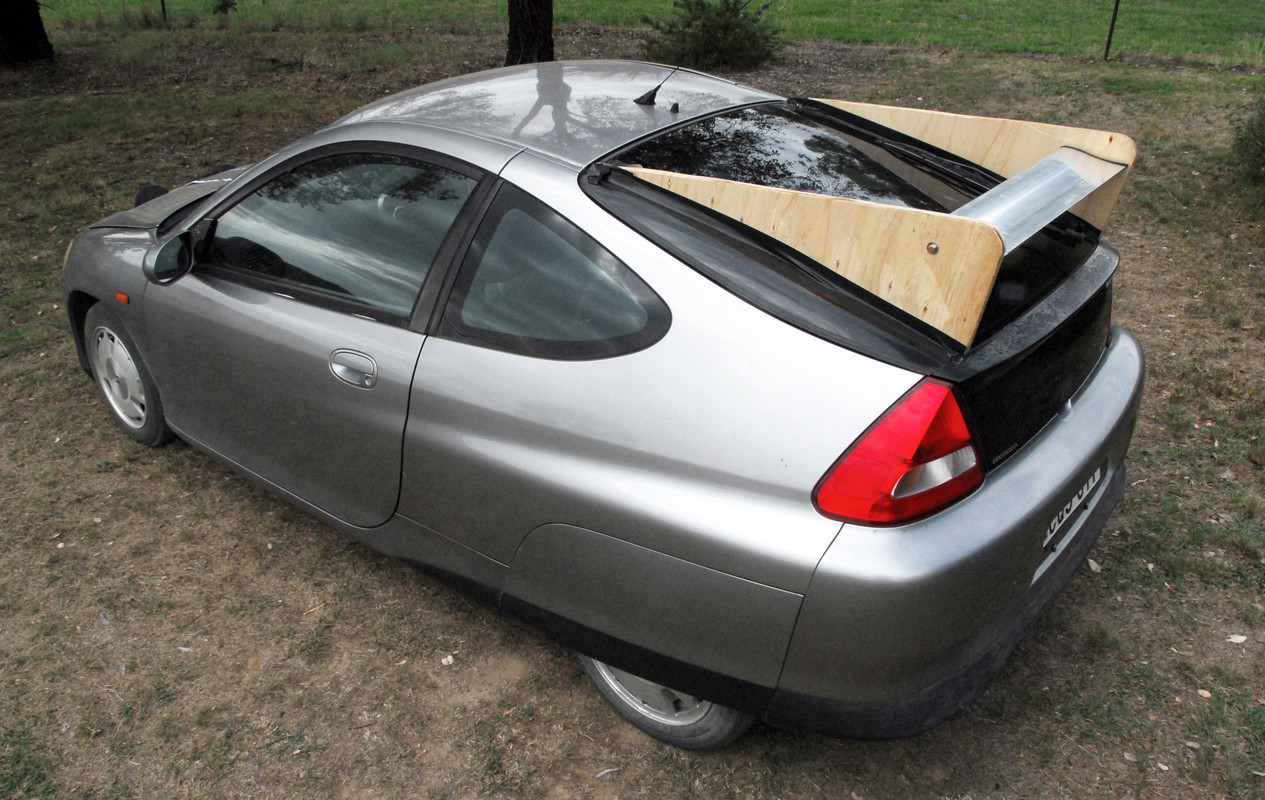
...and then when I found they worked, making the fins from clear acrylic. (Clear fins are actually cited in a 1930s patent for those Kamm cars!)
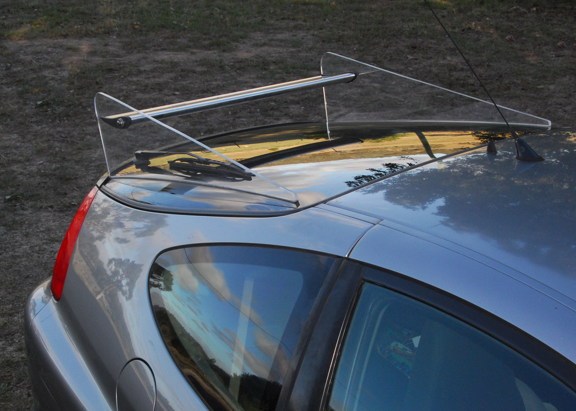
The fins work really well at improving stability, so a win-win all-round.
Old technical aero books and papers can be a wonderful source of ideas - and are often fascinating in just a pure engineering history context - but as soon as you start uncritically applying this material to modern cars, you're on very shaky ground. That's especially the case when quoting data like drag or lift changes, or implicitly assuming that airflow patterns on those cars and the cars of today are similar. They might be - or much more likely, might not be.
But as a source of ideas to then be tested in a modern context? Great!
Last edited by JulianEdgar; 05-17-2020 at 06:14 PM..
|
|
|

|
|
The Following User Says Thank You to JulianEdgar For This Useful Post:
|
|
 05-18-2020, 02:43 AM
|
#8 (permalink)
|
|
Banned
Join Date: Nov 2017
Location: Australia
Posts: 2,060
Thanks: 107
Thanked 1,608 Times in 1,137 Posts
|
In the first post in this thread I nominated objective testing techniques - testing that either uses numbers (eg speed in throttle-stop testing) or applies concrete criteria (eg determining whether flow is attached or separated in wool tuft testing).
But subjective testing is also very important.
In a previous life, when I wrote new car tests, almost all the tests I wrote were subjective. We used fuel economy and performance figures, but all the rest was subjective. Handling balance, steering feel, ride quality - even the ergonomics - were judgements that I (and usually a colleague - we'd share the car over the week) made.
As my experience in testing cars grew, I think my judgements improved, but the tests largely remained just my opinion. And I was happy with that, as I thought it probably more useful to a typical car buyer than pages of figures.
In car aerodynamics, where possible, I much prefer to use objective data. Measured lift/downforce, measured mileage, measured throttle-stop testing - and so on. But for some criteria, I don't think that works. One good example is car stability. How discombobulated does a car become in gusty crosswinds? How rapidly does steering correction need be applied? When slowly drawing past large vehicles on multi-laned freeways, how distinct is the bow wave of the other vehicle?
And sometimes, it's good to use both objective and subjective testing.
An example that springs to mind is when I put a front undertray on my NHW10 Prius. The NHW10 was the very first Prius, a Japanese-only model that was not sold out of that country. However, here in Australia, some importers were bringing in used cars, and I bought one of them. (So at one stage I owned both 'first' hybrids of the modern era - the NHW10 Prius and the Gen I Insight. This was back in about 2004.)
The front underside of the Prius was pretty bad, and I made an undertray that was (1) much larger than the original, and (2) also much smoother. I first tested a mock-up...
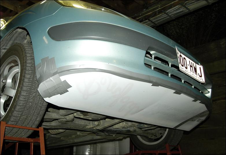
...and measured better highway fuel economy.
I then made the real one, and it worked at least as well as the mock-up.
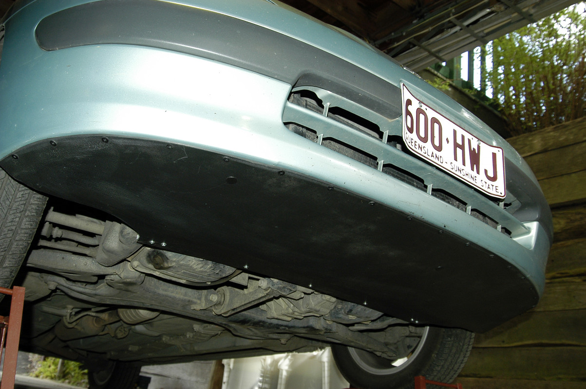
With the new undertray in place, I could detect no major change in stability, although if I had to guess, I would have said it was just a fraction better than standard.
I then thought I might make some trial fairings that could go ahead of the front wheels. My mock-ups looked like this.
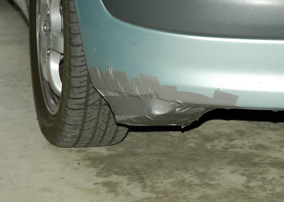
But this time the car's stability was clearly - and adversely - impacted. The car needed more steering correction in crosswinds and, simply, wasn't as poised on the road. So I took them off.
(To me driving stability outweighed any potential mileage gains, so I didn't even bother measuring mileage with them on).
So I would never write-off subjective testing, especially of attributes like aerodynamic stability. |
|
|

|
|
The Following User Says Thank You to JulianEdgar For This Useful Post:
|
|
 05-18-2020, 06:21 PM
|
#9 (permalink)
|
|
Banned
Join Date: Nov 2017
Location: Australia
Posts: 2,060
Thanks: 107
Thanked 1,608 Times in 1,137 Posts
|
Testing can be very easy and cheap.
I've previously measured the downforce created by the rear wing on my Insight by measuring suspension deflection. But, because the wing is mounted on the rear hatch, I thought I'd try an even simpler method.
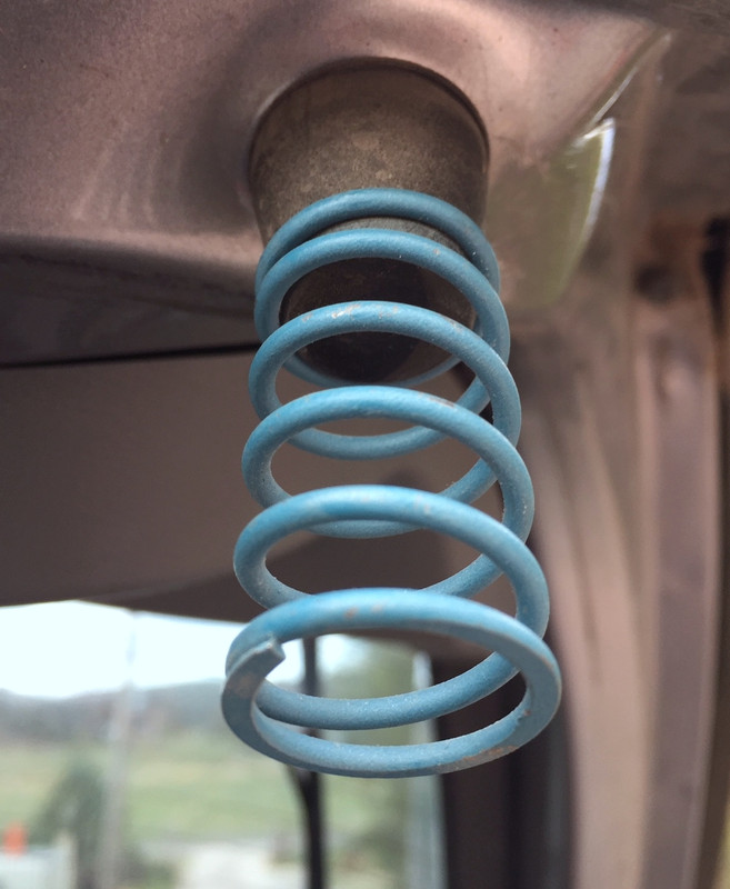
I placed some springs on the rubber bump mounts of the hatch...
..and then placed a vertical, marked piece of wood inside the car, near the vertical part of the hatch. I placed a piece of tape on the rear glass, aligning it at the zero mark.
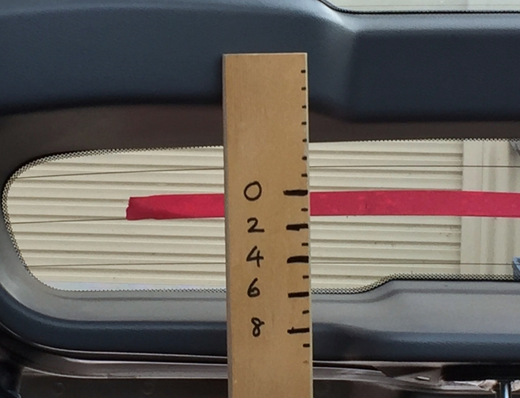
The vertical scale and mark were visible in the rear vision mirror.
I then drove the car, altering the wing angle against a bubble level scale for each test....
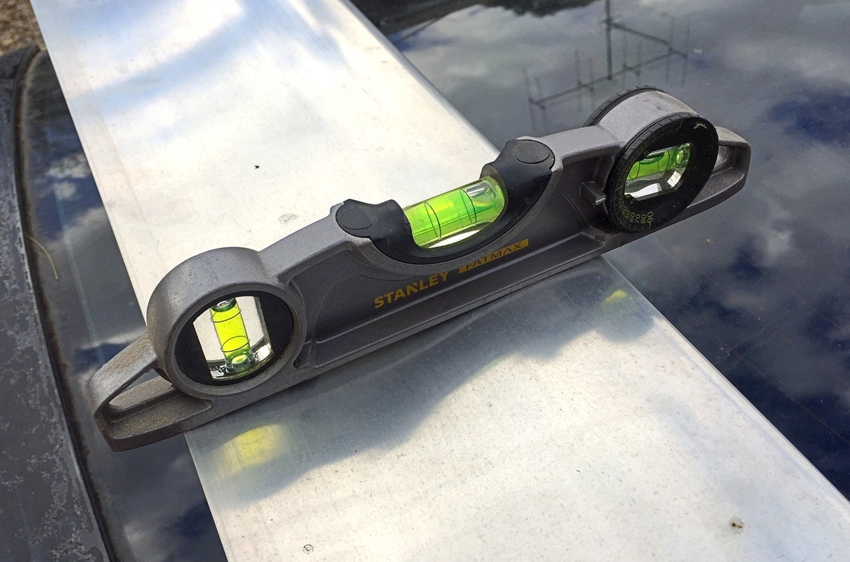
...until I could see in the rear vision mirror when the wing caused the maximum compression of the hatch on the springs.
Back home, I then added weights to the wing until the compression was the same as the maximum recorded on the road.

So an easy way of measuring:
(1) best wing angle for maximum downforce
(2) the actual amount of of downforce created by the wing
And on the Honda?
(1) 0 to minus 5 degrees reference angle
(2) 8kg downforce at 100 km/h (18lb at 62mph)
Off topic addition:
Once you have real, measured data, you can then apply theory with some confidence.
Aero forces go up with the square of the speed. So at 150 km/h (air speed, remember, so that could be 130 km/h road speed and a 20 km/h headwind), the rear downforce created by the wing has increased to (150/100)^2, or 2.25 times. That is, it has increased from 8 to 18kg.
Given that I am already gaining true downforce from the undertray, the wing adds 'too much of a good thing' - especially when its downwards force is behind the rear axle line (and so helping to lift the front).
Therefore, I typically run with the wing producing little or no downwards force. (But it is still needed to hold the fins vertical.)
(And at 200 km/h and set for maximum downforce? 32kg (70lb). And that would definitely be too much of a good thing!)
Last edited by JulianEdgar; 05-18-2020 at 06:53 PM..
|
|
|

|
|
The Following User Says Thank You to JulianEdgar For This Useful Post:
|
|
 05-19-2020, 03:02 AM
|
#10 (permalink)
|
|
Banned
Join Date: Nov 2017
Location: Australia
Posts: 2,060
Thanks: 107
Thanked 1,608 Times in 1,137 Posts
|
I received some more GOE222 aluminum aerofoil today - two 1.6m (5.25ft) lengths.
For interest's sake, I thought it might be good to have the aerofoil projecting vertically through the sunroof of my wife's car, as she drove at 50 km/h (31 mph).
By rotating the aerofoil I could then get a (literal) feel for the forces involved. It was quite fascinating.
It was easy to set the aerofoil to an angle where basically no drag could be felt, but by rotating it a little you could get an amazing amount of sideways force (ie lift or downforce if the wing were horizontal).
I was really surprised with how hard it was to stop it moving sideways. That's what it wanted to do - as the official lift/drag figures show, even when developing max lift/downforce, the drag isn't very high (ie it didn't much want to move backwards).
So no figures (I have done 'proper' measurements on multiple other occasions with this extrusion) but a startling indication of the forces that can be developed.
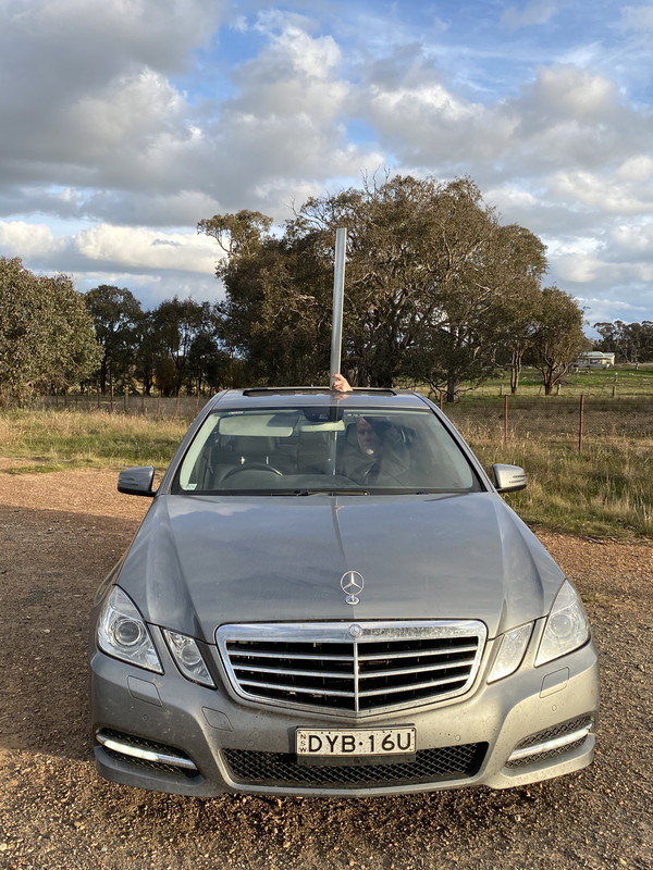
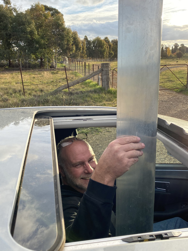
So there's a test I haven't done before.
Last edited by JulianEdgar; 05-19-2020 at 04:28 AM..
|
|
|

|
|
The Following User Says Thank You to JulianEdgar For This Useful Post:
|
|
|