05-19-2020, 10:48 AM
|
#11 (permalink)
|
|
Somewhat crazed
Join Date: Sep 2013
Location: 1826 miles WSW of Normal
Posts: 4,564
Thanks: 596
Thanked 1,253 Times in 1,105 Posts
|
The airfoils ZERO LIFT angle can be roughly calculated by an imaginary line from the tail through the high point of the Camber line but the zero lift line is not lowest drag AOA. Any good airfoil ordinate data plot can show the AOA for minimum drag and zero lift.
|
|
|

|
 Today Today
|
|
|
|
 Other popular topics in this forum...
|
|
|
|
|
05-19-2020, 05:02 PM
|
#12 (permalink)
|
|
Banned
Join Date: Nov 2017
Location: Australia
Posts: 2,060
Thanks: 107
Thanked 1,608 Times in 1,137 Posts
|
Quote:
Originally Posted by Piotrsko

The airfoils ZERO LIFT angle can be roughly calculated by an imaginary line from the tail through the high point of the Camber line but the zero lift line is not lowest drag AOA. Any good airfoil ordinate data plot can show the AOA for minimum drag and zero lift.
|
Yes, all the data curves are available - GOE 222 (MVA H.33) AIRFOIL (goe222-il) |
|
|
|
|
05-19-2020, 05:17 PM
|
#13 (permalink)
|
|
Banned
Join Date: Nov 2017
Location: Australia
Posts: 2,060
Thanks: 107
Thanked 1,608 Times in 1,137 Posts
|
And further to poking things out of sunroofs...
A few years ago I compared the drag of two rear vision mirrors using this rig.
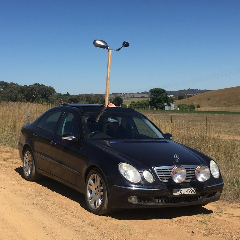
The approach was to move the vertical pole's attachment to the cross-arm closer to one mirror until, under the influence of the airflow, the pole no longer wanted to rotate ie the assembly no longer developed a torque. By looking at the ratio of the distance from the centre of each mirror to the vertical, the relative drag values could be calculated.
In this case, the Honda Insight mirror (left) had about 1.5 times the total (CdA) drag of the Yamaha R6 mirror.
By then measuring projected frontal area, the difference in Cd could also be calculated. This showed the Honda mirror to have a Cd about 20 per cent lower than the Yamaha mirror.
So, because of its shape and size, the Insight mirror had a greater total drag but a lower Cd.
You could also compare a mirror to an object having a known frontal area and Cd eg a flat plate.
Note that this test compares the drag of the mirrors in isolation - not when attached to the car.
A similar 'rotating axis' approach was used by the Wright Brothers to investigate the performance of aerofoils. They used a bicycle as the moving vehicle. |
|
|
|
|
The Following 2 Users Say Thank You to JulianEdgar For This Useful Post:
|
|
|
05-20-2020, 02:58 AM
|
#14 (permalink)
|
|
Banned
Join Date: Nov 2017
Location: Australia
Posts: 2,060
Thanks: 107
Thanked 1,608 Times in 1,137 Posts
|
The interesting thing about testing is that it can show you that what you were quite confident was working, perhaps isn't.
The rear diffuser on the Insight is angled upwards at about 10 degrees, a figure within the range supported by the tech literature. (But as I always say, all such angles are car-dependent.) The undertray as a whole works very well, giving measurable overall car downforce. (I am prepared to trade off the extra drag for the downforce.) I had always assumed that the diffuser's performance was part of that effective undertray - but perhaps not.
The first clue was that when I put longitudinal strakes in the diffuser, it made no difference the undercar measured pressures.
But today's test was more significant.
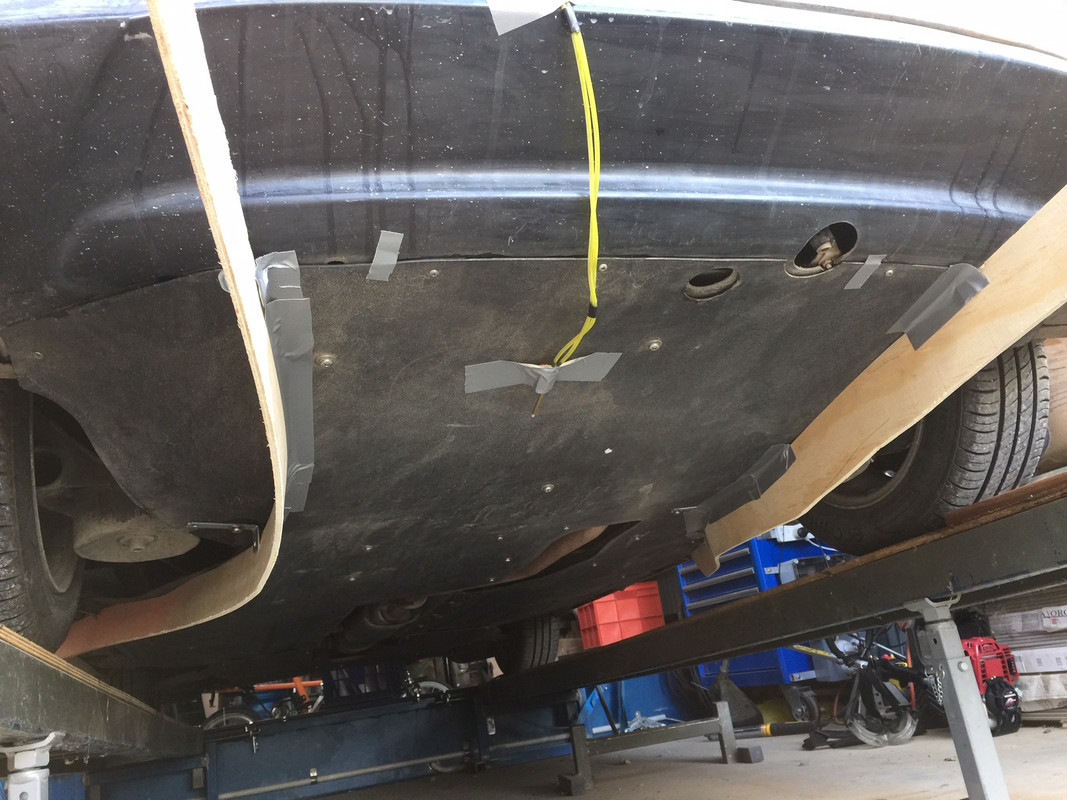
I wool tufted the diffuser section of the undertray and took some pics. They're hard to take because you basically need to lie on the ground and snap the shutter as the car drives past. The day was also very dull - I'll try to redo the pics if tomorrow is bright and sunny!
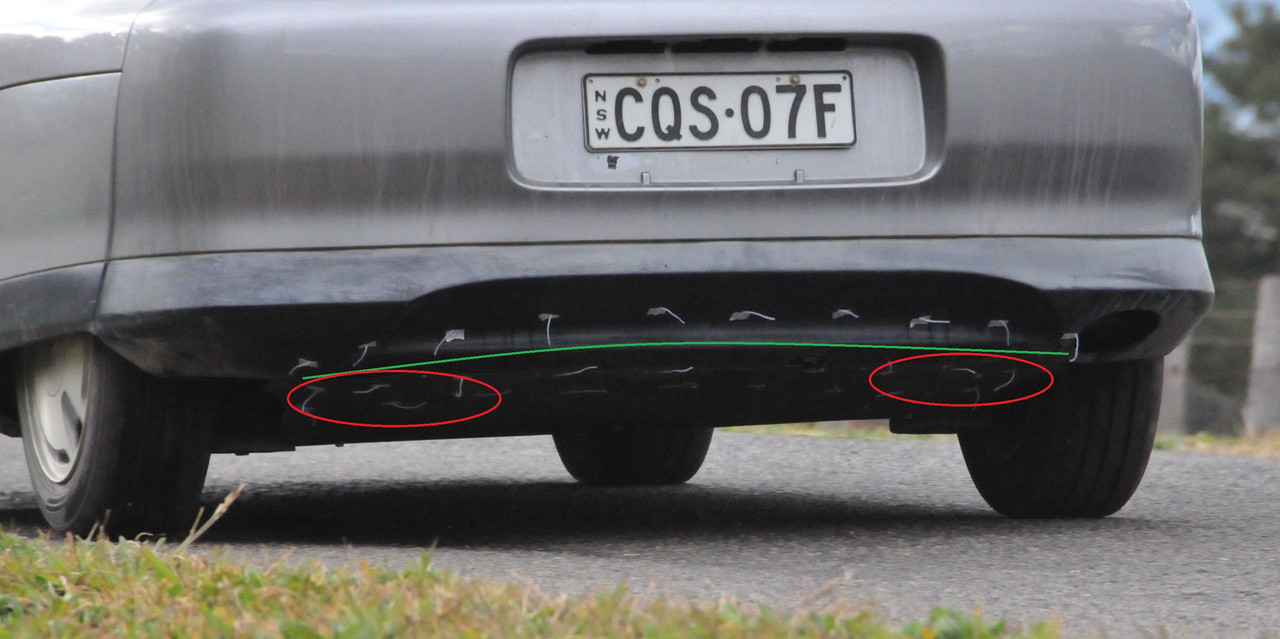
The first thing that can be seen is that the tufts on the lower bumper (ie above the green line) are all in separated flow - not unexpected. But what is startling is the separated flow on either side of the diffuser (red ellipses). The central part of the diffuser seems to have attached flow, but not the sides.
I think someone here (freebeard?) suggested previously that the rear wheel wakes might cause a disturbance to flow on the diffuser, and it certainly looks like that. I also thought that perhaps the lower seats of the air springs might be causing flow problems.
So I added some angled strakes down each side to separate the wheel wakes and lower spring seats from the diffuser flow. (I also deleted the top row of tufts.)
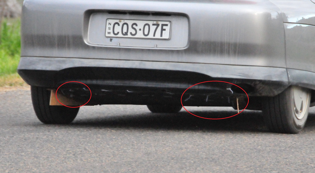
But as can be seen, the pattern is effectively no different.
So tomorrow I might make some mock-ups that reduce the upwards angle of the diffuser and see if I get can attached flow right across its width. Perhaps two lower-angled ramps each side?
 |
|
|
|
|
The Following 2 Users Say Thank You to JulianEdgar For This Useful Post:
|
|
|
05-20-2020, 12:07 PM
|
#15 (permalink)
|
|
Master EcoModder
Join Date: Jun 2009
Location: SC Lowcountry
Posts: 1,796
Thanks: 226
Thanked 1,354 Times in 711 Posts
|
.
Nice... 
Quote:
|
I wool tufted the diffuser section of the undertray and took some pics. They're hard to take because you basically need to lie on the ground and snap the shutter as the car drives past.
|
Maybe mount a small camera like a cheap backup or dash cam video camera to see or record whats happening instead of trying to take pictures as the vehicle passes. If your think the camera or mounts might affect the air flow patterns then something else may be needed. In the movie industry when rolling action shots are needed, the cameras are often mounted to a Jib on another vehicle. A jib being a long supported pole. Several pieces of 1/2 EMT (electrical metal tubing) welded or bolted together in a triangular shape and mounted solidly to the front of a second vehicle with the camera mounted low should work nicely and would be easy to fabricate.
Again, just spitballing...

>
.
__________________
Woke means you're a loser....everything woke turns to ****.
Donald J Trump 8/21/21
Disclaimer...
Im not a climatologist, aerodynamicist, virologist, physicist, astrodynamicist or marine biologist..
But...
I play one on the internet.

|
|
|
|
|
The Following User Says Thank You to redneck For This Useful Post:
|
|
|
05-20-2020, 05:58 PM
|
#16 (permalink)
|
|
Banned
Join Date: Nov 2017
Location: Australia
Posts: 2,060
Thanks: 107
Thanked 1,608 Times in 1,137 Posts
|
Quote:
Originally Posted by redneck
.
Nice...
Maybe mount a small camera like a cheap backup or dash cam video camera to see or record whats happening instead of trying to take pictures as the vehicle passes. If your think the camera or mounts might affect the air flow patterns then something else may be needed. In the movie industry when rolling action shots are needed, the cameras are often mounted to a Jib on another vehicle. A jib being a long supported pole. Several pieces of 1/2 EMT (electrical metal tubing) welded or bolted together in a triangular shape and mounted solidly to the front of a second vehicle with the camera mounted low should work nicely and would be easy to fabricate.
Again, just spitballing...
>
. |
I tried using a Go Pro video camera about 3 years ago to look at tufts on the undertray but the angle was so small that you couldn't see anything. I couldn't have the camera any lower or it was in danger of hitting the road.
I am thinking of using a miniature pitot tube (yet to be covered in this thread on measuring techniques) where airspeed should be able to be used to determine if flow is attached or separated. |
|
|
|
|
05-20-2020, 11:29 PM
|
#17 (permalink)
|
|
Banned
Join Date: Nov 2017
Location: Australia
Posts: 2,060
Thanks: 107
Thanked 1,608 Times in 1,137 Posts
|
Well, that was interesting. I've just done some testing with my model aircraft pitot tube. (A pitot tube measures airspeed. The higher the pressure differential across its ports, the higher the airspeed.)

I placed the pitot tube in the diffuser area that tuft testing had yesterday shown had attached flow (ie the central area of the diffuser). I spaced the pitot tube about 10 mm off the surface so I wasn't just measuring boundary layer. At 70 km/h I recorded a pressure differential across the pitot tube ports of 90 pascals.
I then moved the pitot tube to one of the side areas that yesterday's tuft testing had shown having separated flow. At 70 km/h the reading was zero, with a high speed, tiny flutter in the needle.
So yes, a pitot tube can be used to show areas of attached and separated flow under the car.
I then made some long, deep and curved strakes.
These are deeper than I could ever run on the road, but in testing I have found it's always better to go big first and see what happens. So what did happen?
The airspeed recorded in the central position of the diffuser increased. The pressure across the ports was 125 Pascals at 70 km/h, an increase of about 40 per cent. At the inner edge of the strake, the pitot tube showed even higher speeds - I was off the max of the meter (125 Pa) at 70 km/h and had to drop to 60 km/h to get back to 125 Pa.
Note the tape marked with the arrows.
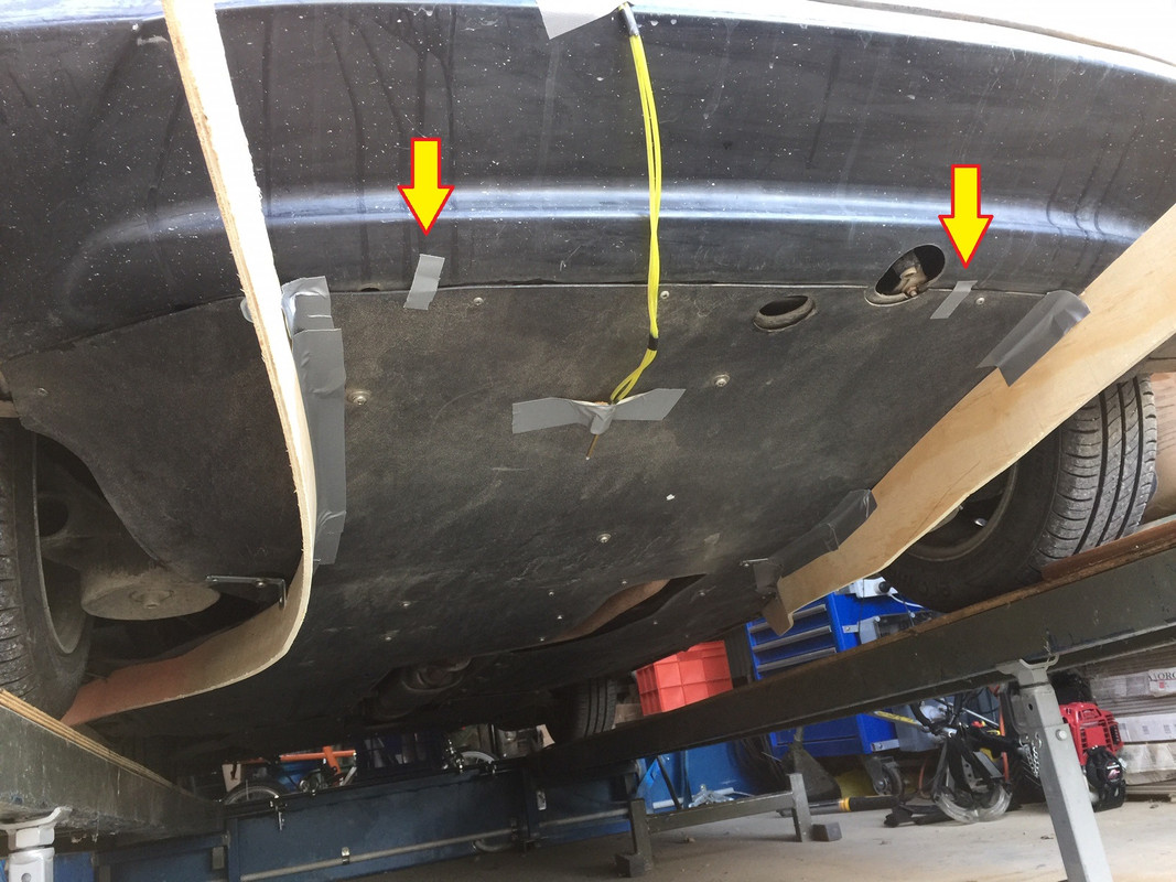
These arrows show the approximate widest positions where attached flow was occurring prior to the strakes being used. Therefore, with the curved strakes the:
- airspeed through the diffuser has increased
- a greater width of the diffuser has attached flow |
|
|
|
|
05-21-2020, 03:28 AM
|
#18 (permalink)
|
|
Banned
Join Date: Nov 2017
Location: Australia
Posts: 2,060
Thanks: 107
Thanked 1,608 Times in 1,137 Posts
|
So, 4 metres of EPDM rubber, 38mm x 19, and a can of contact adhesive.

I'll glue it on edge to the undertray for the 'curvy strakes'.
It may not be deep enough, but I could never run as deep as the plywood trial ones, so it will have to do.
Tomorrow's job!
Last edited by JulianEdgar; 05-21-2020 at 05:35 AM..
Reason: expository comma
|
|
|
|
|
05-21-2020, 03:41 AM
|
#19 (permalink)
|
|
Banned
Join Date: Nov 2017
Location: Australia
Posts: 2,060
Thanks: 107
Thanked 1,608 Times in 1,137 Posts
|
Pitot tube - measure airflow speed
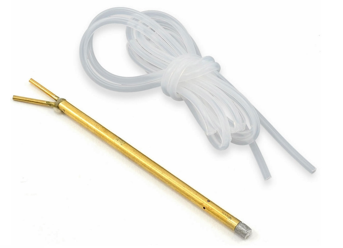
Example uses: Find areas of separated and attached flow, measure thickness of boundary layers, assess airflow direction for setting wing angles
Equipment: model aircraft pitot tube, sensitive Magnehelic gauge
Complexity: easy to do and interpretation of results straightforward
Comment: allows assessment of attached / separated flow on undertray out of sight of wool tufts
Cost: $10 (pitot) + $50 (gauge)
(I must credit F1 aerodynamicist Willem Toet for bringing these pitot tubes to my attention. He mentioned them to me when describing some low cost data logging equipment being used in student-based racing cars. I didn't go for the data logging equipment, but loved the pitot tubes!)
Last edited by JulianEdgar; 05-21-2020 at 04:06 AM..
Reason: Addition
|
|
|
|
|
05-21-2020, 07:31 AM
|
#20 (permalink)
|
|
106 diesel enthusiast
Join Date: Apr 2020
Location: Scotland
Posts: 10
Thanks: 9
Thanked 3 Times in 2 Posts
|
Quote:
Originally Posted by JulianEdgar
I tried using a Go Pro video camera about 3 years ago to look at tufts on the undertray but the angle was so small that you couldn't see anything. I couldn't have the camera any lower or it was in danger of hitting the road.
I am thinking of using a miniature pitot tube (yet to be covered in this thread on measuring techniques) where airspeed should be able to be used to determine if flow is attached or separated.
|
a-HA! There's a solution to the camera problem.
universal reversing camera kit, very small and come with 4 bright LED's, in full colour too! regular video output via RCA so you can even record it. The camera itself is about 25mm square so it's quite unobtrusive and it's got a relatively wide angle.
I got a pair for the equivalent of $100AU. 2 cameras, cables and 2 screens. I actually bought them for doing a wing mirror delete, but I'm going to use them for looking at the underside of my car when I get round to creating a good flat floor and diffuser.
|
|
|
|
|