 12-03-2014, 08:14 PM
|
#1361 (permalink)
|
|
EcoModding Apprentice
Join Date: Nov 2012
Location: East Midlands
Posts: 180
Thanks: 13
Thanked 81 Times in 52 Posts
|
Quote:
Originally Posted by Astro

I used to do the same.
When i used to use the soldering iron for SMD i would sometimes get the components preferring to stick to the tip of the soldering iron rather than the PCB pad.
Also it was difficult to remove components. Many times i found myself heating one end of a resistor then quickly trying to heat the other end before the first end cooled enough to solidify again.
Then, when i contemplated doing all my BMS cell top boards (lots of boards and lots of SMD components) i thought i would treat my self to the hot air station. Always looking for justification to buy more tools. 
I should have done it years ago. The hot air makes it so easy, neat and clean.
On one of the first few boards i did i manage to solder the pic micro in reversed. Doh.
With just a soldering iron this would have been a pain to fix without risking heat damage to the micro and probably making a mess of the board. With the hot air wand it only took a few seconds to heat it, lift it, rotate it and re-place it. Couldn't even tell it had been reworked afterwards. From then on i was a huge fan of hot air soldering.
The solder paste is brilliant as well. Each pad gets just the right amount of solder.
The couple of times i did get a solder bridge between micro pins. All i did was reheat the area for a couple of seconds and boom solder bridge gone. The flux in the solder paste really works well. The solder runs to the pad and component leg as if it was magnetised.
Mesmerising to watch.
Also the solder paste holds the component perfectly. I can pick and place the entire board before soldering without fear that i will bump the PCB and have the components move around. It also means i don't have to keep swapping between soldering and pick and placing.
I firstly place all the components one after another on all the boards,then when i finish that i move on to the heat gun. So the first step is just using the tweezers and the second step is just using the heat gun.
I was picking and placing between 10 and 20 boards at a time. This made the process much quicker and also reduced error as i would place the same component on each of the boards in turn then select the next component and place it on each of the boards in turn.
When i do have to solder a through hole component the solder station has a nice temperature controlled soldering iron as well. 
It was $70 well spent. |
I second that. Hot Air serves as a dual purpose to remove or re-work only some components. And one doesn't risk overheating a component for too much time or wife complaining about our cooking in the oven 
|
|
|

|
 Today Today
|
|
|
|
 Other popular topics in this forum...
|
|
|
|
|
12-03-2014, 09:07 PM
|
#1362 (permalink)
|
|
Master EcoModder
Join Date: Sep 2010
Location: Saskatoon, canada
Posts: 1,488
Thanks: 746
Thanked 565 Times in 447 Posts
|
Quote:
Originally Posted by MPaulHolmes
..Would one of the 2 beta testers be willing to wait a little longer while I get an encoder on it, and test the controllers on that? It's rated for 45amp (so a higher current test!!), and I haven't had the opportunity to get FOC working with brushless DC.
|
It sounds like both of us would be OK to have you test the controllers now that you have a motor to test with.
Ship the controller when you can - I never get things done as quickly as I think I can anyway. |
|
|
|
|
12-03-2014, 09:21 PM
|
#1363 (permalink)
|
|
Master EcoModder
Join Date: Sep 2010
Location: Saskatoon, canada
Posts: 1,488
Thanks: 746
Thanked 565 Times in 447 Posts
|
Quote:
Originally Posted by cts_casemod
V/Hz is just a dumb term that is incorrectly used by manufactures to define a controller with no intelligence of its own.
|
OK
Quote:
The technical name is scalar control and just derives that for a decrease in frequency one has to reduce the voltage as well to keep the same magnetic flux, which is also true for Field Oriented Control.
Scallar control can be modified to use in a vehicle. Closed loop control, space vector modulation and adaptive output voltage are used to achieve great efficiency.
|
The industrial AC controllers I've used have no option for encoder input on V/Hz. You can select a pump load (cubic curve), a fan load (squared curve) or a constant torque load (linear). There is an offset for the voltage to start at 0 Hz, usually called boost. As the frequency setpoint is raised, the voltage output is raised according to the type of load selected. And that's about it for control.
There are also a bunch of parameters for what frequency the boost cuts out, what the starting frequency is, frequencies to skip, aceeleration and deceleration rates, etc etc
Quote:
|
One doesn't necessarily need Field Oriented Control to achieve good performance, although it makes development easier between different motor types.
|
No tuning when changing motors is the big advantage. An electrician can change out the motor without calling a tech to tune the drive to the new motor. Paul's version of tuning measures a rotor constant, inductance of the stator ... and something else that I don't remember right now
Quote:
|
Now if by V/Hz you want to say 'open loop scalar control', yes that's pretty much un-driveable on a road vehicle unless the driver has some practice. Its not something nice though.
|
OK. Open loop scalar is the term. I learned something today!
I would like feedback to the tach on the dash.
Not sure if it would be undriveable, but it would certainly be different to accelerate or decelerate at a maximum programmed rate each time you change the throttle more than 1% or 2%, until the car is at the 'new' setpoint speed.
I might like to try it, just to see how different it is. |
|
|
|
|
The Following 2 Users Say Thank You to thingstodo For This Useful Post:
|
|
|
12-03-2014, 10:26 PM
|
#1364 (permalink)
|
|
PaulH
Join Date: Feb 2008
Location: Maricopa, AZ (sort of. Actually outside of town)
Posts: 3,832
Thanks: 1,362
Thanked 1,202 Times in 765 Posts
|
I have some open loop code somewhere. It's really simple. We should definitely try it out. It would be fun to compare. The serial and EEProm ("reprimand" was from the very helpful cell phone) stuff is really cleaned up and ready to test. I added numberOfPolePairs, currentSensorAmpsPerVolt, rotorTimeConstantIndex, and a few others that I forgot at the moment, so there are 18 different programmable settings. I need to add throttle type to the list. It's set up for Hall effect only, but I will add 0-x ohm and x to zero ohm throttles as options.
Last edited by MPaulHolmes; 12-04-2014 at 10:13 AM..
|
|
|
|
|
The Following 2 Users Say Thank You to MPaulHolmes For This Useful Post:
|
|
|
12-04-2014, 08:02 AM
|
#1365 (permalink)
|
|
EcoModding Apprentice
Join Date: Nov 2012
Location: East Midlands
Posts: 180
Thanks: 13
Thanked 81 Times in 52 Posts
|
Quote:
Originally Posted by thingstodo
Not sure if it would be undriveable, but it would certainly be different to accelerate or decelerate at a maximum programmed rate each time you change the throttle more than 1% or 2%, until the car is at the 'new' setpoint speed.
I might like to try it, just to see how different it is.
|
My first inverter was open loop and worked exactly as you say. One had to adjust the throttle in 1 or 2% setpoints, but even that was not enough to avoid huge currents or the motor to loose sync during field weakening. Plus if one released the throttle the motor would act as a huge brake.
In practice to make it useful I used a speed ramp to ramp the speed up and down slowly and absorb any peaks, for example if one goes over a bump the throttle is going to jump a bit as well. The problem with the speed ramp is that if you are not able to have separate settings for acceleration and deceleration a ramp which is good for acceleration is too slow for the deceleration required and one ends up slamming the brakes against the motor during a fast stop.
In practice is never going to be nice to drive and requires the car to be undrivable by anyone but you.
Many industrial drives use current (amps) feedback to achieve a crude speed ramp closed loop, but this only works below nameplate speed. |
|
|
|
|
The Following 3 Users Say Thank You to cts_casemod For This Useful Post:
|
|
|
12-06-2014, 03:16 AM
|
#1366 (permalink)
|
|
PaulH
Join Date: Feb 2008
Location: Maricopa, AZ (sort of. Actually outside of town)
Posts: 3,832
Thanks: 1,362
Thanked 1,202 Times in 765 Posts
|
Serial and EEPROM are now working. Here's a quick video of it. My junky iPhone that I wish I never got had no space on it, so it had to be kept short. Also, it was tested at 120v nominal dc input. So far so good.
Here's some serial data:
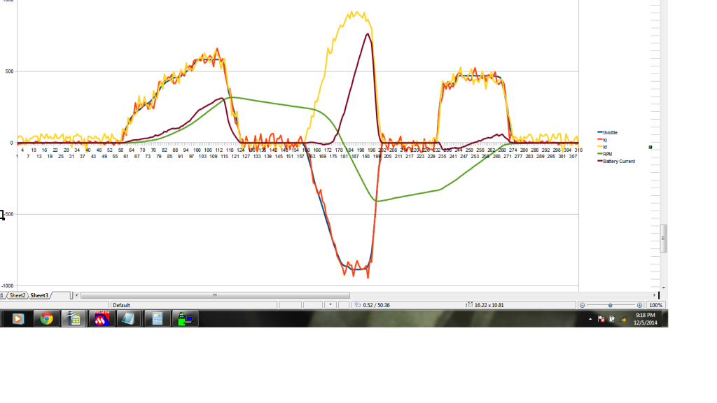
Here is serial data of rpm from zero to full throttle.
 |
|
|
|
|
The Following 3 Users Say Thank You to MPaulHolmes For This Useful Post:
|
|
|
12-06-2014, 07:20 AM
|
#1367 (permalink)
|
|
Dreamer
Join Date: Nov 2013
Location: Australia
Posts: 350
Thanks: 95
Thanked 214 Times in 151 Posts
|
Well done. 
The RPM looks very smooth, no jerky fluctuations.
In the first chart the negative throttle was much higher that the positive throttle.
What percentage of full throttle were they?
Was that done with a 0-5k pot as the throttle or a 0-5v hall effect throttle? |
|
|
|
|
12-06-2014, 10:27 AM
|
#1368 (permalink)
|
|
PaulH
Join Date: Feb 2008
Location: Maricopa, AZ (sort of. Actually outside of town)
Posts: 3,832
Thanks: 1,362
Thanked 1,202 Times in 765 Posts
|
That was never close to full throttle in either direction. I was trying to keep it out of field weakening territory to get a more realistic picture of the behavior at much higher voltage. This is a Hall effect throttle at the moment. I also made it programmable so you can use x ohms to y ohms, where x and y can be anything. For example 0-5k or 5k - 0 throttle would be fine.
|
|
|
|
|
The Following 2 Users Say Thank You to MPaulHolmes For This Useful Post:
|
|
|
12-06-2014, 12:29 PM
|
#1369 (permalink)
|
|
Master EcoModder
Join Date: Sep 2010
Location: Saskatoon, canada
Posts: 1,488
Thanks: 746
Thanked 565 Times in 447 Posts
|
Quote:
Originally Posted by MPaulHolmes
Serial and EEPROM are now working. Here's a quick video of it...Also, it was tested at 120v nominal dc input. So far so good.
|
AWESOME!
That is beautiful control. Is that with the 2.5HP PMSM motor? |
|
|
|
|
12-06-2014, 12:42 PM
|
#1370 (permalink)
|
|
PaulH
Join Date: Feb 2008
Location: Maricopa, AZ (sort of. Actually outside of town)
Posts: 3,832
Thanks: 1,362
Thanked 1,202 Times in 765 Posts
|
No this is the 6kw 480vac motor at 120vdc bus. I am waiting on payday to order an encoder for the brushless dc motor. I tested the brushless motor by spinning the post and looking at the waveform on the oscilloscope. It looked very sinewavish so it will be fun to test it .
|
|
|
|
|
The Following User Says Thank You to MPaulHolmes For This Useful Post:
|
|
|


