02-23-2009, 08:27 AM
|
#431 (permalink)
|
|
Master EcoModder
Join Date: Jun 2008
Location: London, Ontario
Posts: 1,096
Thanks: 0
Thanked 17 Times in 14 Posts
|
Very nicely done, Paul. That mill is really helping you turn out nice work 
Do you have much experience soldering?
Have you considered adding vias to the board?
Is it truely necessary to use SO MUCH copper? What other options would there be for so much current and heat handling? I'm just thinking from a mass-production economics p.o.v.
There is no question, you'll want to use that thermal paste for longevity/safety.
Looking forward to seeing it in action
|
|
|

|
 Today Today
|
|
|
|
 Other popular topics in this forum...
|
|
|
|
|
02-23-2009, 09:28 AM
|
#432 (permalink)
|
|
PaulH
Join Date: Feb 2008
Location: Maricopa, AZ (sort of. Actually outside of town)
Posts: 3,832
Thanks: 1,362
Thanked 1,202 Times in 765 Posts
|
Quote:
Originally Posted by MazdaMatt

Very nicely done, Paul. That mill is really helping you turn out nice work
Do you have much experience soldering?
Have you considered adding vias to the board?
Is it truely necessary to use SO MUCH copper? What other options would there be for so much current and heat handling? I'm just thinking from a mass-production economics p.o.v.
There is no question, you'll want to use that thermal paste for longevity/safety.
Looking forward to seeing it in action |
Hey MazdaMatt! I have very little experience soldering. I just know the basics. Is a via a path for current to flow from one side to the other of a pcb? That's part of the function of the brass bolts. I think the copper heat spreader is not necessary. Aluminum would probably work just fine. The copper bus bars could be more narrow, and then widen on the outside of the controller to allow for bolting lugs to them.
One option for heat handling would be liquid cooling which really isn't that complicated. Just drill a U shape (with a little trickiness) in an aluminum heat spreader, and run water through it with a small pump. Make sure there's a little water reservoir outside the controller. That would eliminate the cost of the external heat sink too.
Another heat handling option is to eliminate the freewheel diodes, and use mosfets. The mosfet acts like a diode. Current can always flow from source to drain, but not drain to source. So, when you want one to conduct from source to drain, it goes through the "body diode" momentarily until you turn it on. Then there is almost no heat loss (whereas the freewheel diode has lots of loss here). When you want it to start blocking current that's coming the other way, just shut it off (bring gate back to 0v). It's called Synchronous Rectification. There's an AVR that has special features to make SR easier. It only comes in surface mount format, though. I ordered some solder paste. I need to learn how to mount surface components. |
|
|
|
|
02-23-2009, 09:53 AM
|
#433 (permalink)
|
|
Administrator
Join Date: Dec 2007
Location: Germantown, WI
Posts: 11,203
Thanks: 2,501
Thanked 2,590 Times in 1,556 Posts
|
It looks great Paul. I'm really looking forward to seeing how this turns out!  |
|
|
|
|
02-23-2009, 10:29 AM
|
#434 (permalink)
|
|
Master EcoModder
Join Date: Jun 2008
Location: London, Ontario
Posts: 1,096
Thanks: 0
Thanked 17 Times in 14 Posts
|
Hi Paul,
A via is typically there to flow current from one side to the other, but its secondary purpose is to make solder joints stronger and make better contact. The solder will suck up into the hole and make a very strong connection to the leads inside. They are used on single-sided boards for this purpose.
Your soldering is fine - but with a higher degree of risk (high current, money investment) just be very anal about that solder. I like to clean the tip with a wipe on a wet sponge between every solder joint. Then put a tiny spot of solder on the tip so that heat conducts better off of it, press the tip into both sides of the joint at once to get it hot, then apply solder. I usually apply solder to the opposite side of the pin from the iron - this ensures that i'm getting the heat to melt the solder from the pin and not from the iron. Feed the solder straight in and let the heat spread it out. If it doesn't happily jump where you expect it to, you're short on heat - don't panick, just stop feeding solder for a second and let the heat spread. Don't overdo it though, or you'll burn your board and parts 
SM soldering is MUCH trickier - especially if you opted for lead-free paste. Get a good sharp pointy tip for that work, i use a hook-shaped one. Put paste on each of the pads, then use tweezers to place the part and hold it. I like to slowly heat the pads so the paste can get a "starter" hold on a few pins before i start to put pressure and get the paste to flow completely... make practice parts
You could probably find images and cut-aways of what solder joints should look like and what they shouldn't look like.
I'm glad I could skimp on the copper a little! that looks pricy!
Keep it up! |
|
|
|
|
02-23-2009, 10:29 AM
|
#435 (permalink)
|
|
Master EcoModder
Join Date: Sep 2008
Location: Texas
Posts: 632
Thanks: 0
Thanked 26 Times in 24 Posts
|
Quote:
Originally Posted by MPaulHolmes
A dang copper gave me a ticket a while back. Some people think copper is an element. It's actually made of doughnut grease and pork.
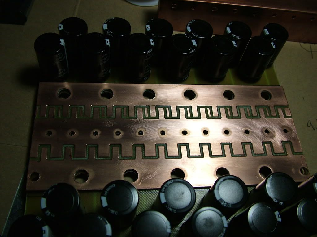
Here's some more pictures of the progress for the power board. I finished soldering the capacitors. It was super easy with a 250 watt (I think) soldering gun from Radio Shack for $30! ya!
This is a picture of it temporarily and partially assembled.
And a side view.
And with an old diode on display. The silver things attached to the copper heat spreader press the diodes/mosfets against it to keep it cool.
The bars with all their dang holes!
With a layer removed.
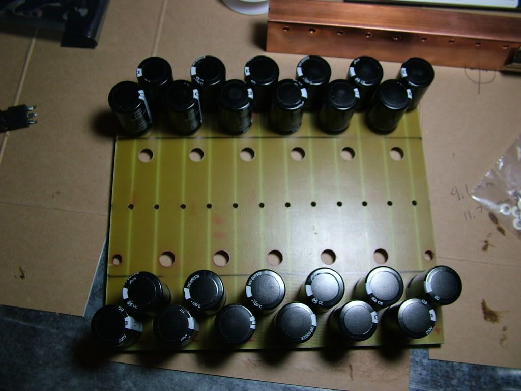
And another layer removed.
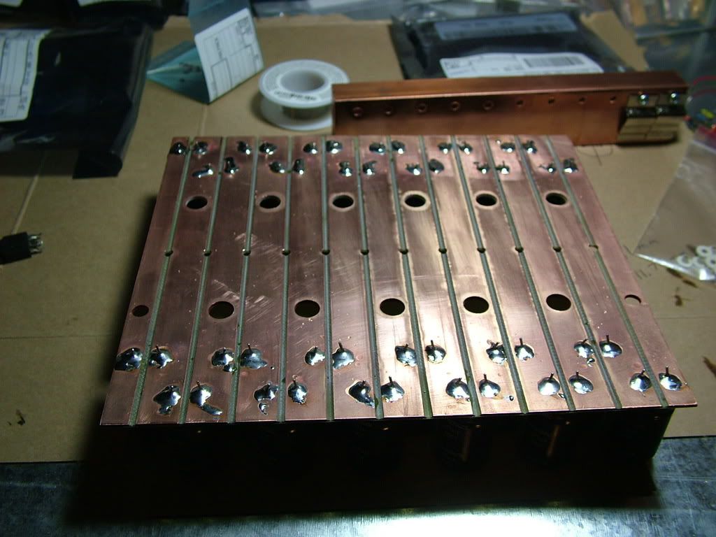
Bottom of capacitor board, with capacitors soldered in place ya!
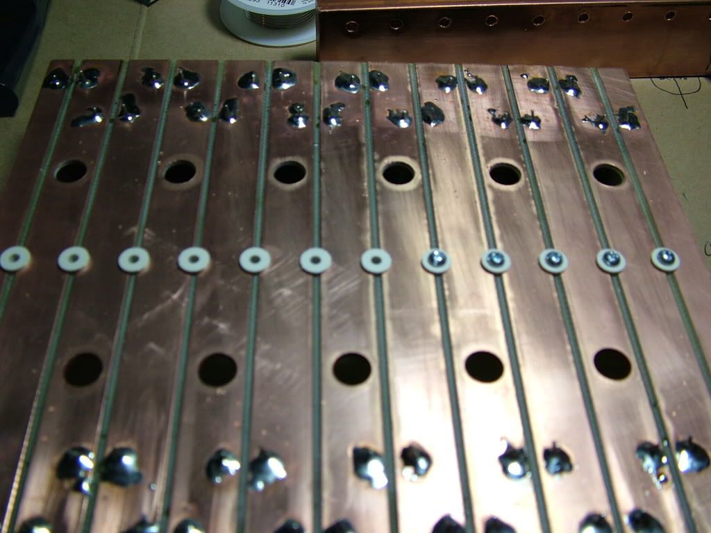
Little plastic things to keep the bolts isolated from the bottom of the board. They are to hold the M- bus bar in place! ya! |
Have you cut out circles out of the copper around the holes covered by the plastic washers to maintain enough clearance from the bolts?
__________________
If America manages to eliminate obesity, we would save as much fuel as if every American were to stop driving for three days every year. To be slender like Tiffany Yep is to be a real hypermiler...
Allie Moore and I have a combined carbon footprint much smaller than that of one average American...
|
|
|
|
|
02-23-2009, 11:00 AM
|
#436 (permalink)
|
|
Master EcoModder
Join Date: Jun 2008
Location: London, Ontario
Posts: 1,096
Thanks: 0
Thanked 17 Times in 14 Posts
|
For the sake of reading, please don't quote with a half-dozen huge images...
Paul... Linky me a reference to synchronous rectification - I want to read up on it and i keep googling into the wrong stuff...
Last edited by MazdaMatt; 02-23-2009 at 11:48 AM..
|
|
|
|
|
02-23-2009, 12:30 PM
|
#437 (permalink)
|
|
EV-FNG
Join Date: Feb 2009
Location: Keene NH
Posts: 4
Thanks: 0
Thanked 0 Times in 0 Posts
|
Images
Hey things are looking good and now that I got a chance at work to see the images on a computer screen instead of my little blackberry screen it makes more sence. I cant wait to get the parts list for the bike controler.
Ben, I just wanted to thank you for all your work too, it was your metro build that got me interested into this field and I'm really excited at what can be done. Well breaks over got to finish this later. Have a good work day guys.
|
|
|
|
|
02-23-2009, 01:56 PM
|
#438 (permalink)
|
|
PaulH
Join Date: Feb 2008
Location: Maricopa, AZ (sort of. Actually outside of town)
Posts: 3,832
Thanks: 1,362
Thanked 1,202 Times in 765 Posts
|
Quote:
Originally Posted by MazdaMatt
Paul... Linky me a reference to synchronous rectification - I want to read up on it and i keep googling into the wrong stuff...
|
I tried searching for it too! I couldn't find anything specific to high power motor controller design. Everything I learned about it was from people on the EVTech list.
According to evtech.org,
"To subscribe to evtech, simply write a message to evtech-subscribe@mailman.evtech.org"
All the fancy people hang out on there. I get regular help from people like Otmar (the maker of the Zilla), Fran (chief engineer of a brushless motor control company), Lee Hart (the Godfather!), Cor van de Water (Director of Harware Systems for some major corporation), etc...! It's pretty awesome.
There are several approaches to SR. The more complicated you want to make it, the more efficient it can be, but it can be done relatively simply.
Basically, you want to remove the diodes, where most of the heat loss comes from. Each one has an approximately fixed voltage drop of like 1 v or something. So, you want to remove the diode, and replace it with a very efficient mosfet, that is carefully controlled so that it mimics the behavior of the diode. Diodes do their diode thing without even thinking about it. Mosfets need a little help.
Let's say you have a PWM duty of 75%. The freewheel diodes have current flowing through them 25% of the time. To copy that behavior, a mosfet needs to be turned on 25% of the time, so current can flow from source to drain with little loss. Current can flow from source to drain anyway, because the mosfet acts like a diode, but it has a lot of loss while acting like a diode. You want to bring the diode mimicking mosfet's gate high as soon as the regular (non-diode mimicking) mosfets' gates are brought low. You could almost use a simple inverted signal of the PWM duty, but you need to throw in a tiny bit of delay, so that the regular mosfets and diode mimicking mosfets are never both on.
I'm going to try it soon, and I'll post the schematic and stuff. If you find any information out about it. I'd love to hear it. Places like Wikipedia say SR is only good for low voltage applications, but that's not true. Because all the mosfets are in parallel, their resistance is much lower. The diodes in parallel, however, still have the same 1v drop! Terrible!
NiHaoMike: Last night I drilled a bigger indent into the bus bars so the bolt heads don't stick out at all. hehe good eye! Now I think I'll insulate the copper heat spreader from the M- bus bar, and glue them together, eventually. |
|
|
|
|
02-23-2009, 02:10 PM
|
#439 (permalink)
|
|
Master EcoModder
Join Date: Jun 2008
Location: London, Ontario
Posts: 1,096
Thanks: 0
Thanked 17 Times in 14 Posts
|
Thanks Paul,
That is basically what i got from the electrical engineer that I asked here at work. She recommended that i research flyback transformers for information. Those are just high-powered coils, too, like a motor.
600A @ 1V = 600W burned off in the diodes...
Say you put together a mere 10 mosfets for flyback - say 0.014ohm each, you'd have effectively 0.0014ohms resistance. 600A @ 0.0014ohm = 504W. Make it 20 mosfets and you're down to .0007ohms and 254 watts. Make it 100 mosfets and you're down to 50W!!! hahahaha!!!
Delay is critical. If you don't delay, you'd have your (say...) 20mosfets and 20 flyback mosfets making a total path resistance of 0.0014 ohms across 144v and now you're burning a lot of heat across this path... 14MW 
I'll post more when I get more details or a good site to read.
-M |
|
|
|
|
02-23-2009, 06:25 PM
|
#440 (permalink)
|
|
Master EcoModder
Join Date: Sep 2008
Location: Texas
Posts: 632
Thanks: 0
Thanked 26 Times in 24 Posts
|
Quote:
Originally Posted by MazdaMatt
That is basically what i got from the electrical engineer that I asked here at work. She recommended that i research flyback transformers for information. Those are just high-powered coils, too, like a motor.
|
The power range for flyback transformers is very, very wide. The smallest I have seen is a Nixie tube supply in a DVD recorder (less than one watt) and the biggest a 48v network power supply (about 1.5kw). PC power supplies (100-500w) have traditionally been half bridge, but most modern ones are flyback for higher efficiency and simpler design. A few hundred watts is generally about the upper practical limit for flyback.
Although a flyback power converter might work well for a battery charger, it would be a poor choice for the main power in an electric car. It would be a good choice for auxiliary power if the amount of auxiliary power is small.
__________________
If America manages to eliminate obesity, we would save as much fuel as if every American were to stop driving for three days every year. To be slender like Tiffany Yep is to be a real hypermiler...
Allie Moore and I have a combined carbon footprint much smaller than that of one average American...
|
|
|
|
|