02-19-2009, 02:12 AM
|
#411 (permalink)
|
|
PaulH
Join Date: Feb 2008
Location: Maricopa, AZ (sort of. Actually outside of town)
Posts: 3,832
Thanks: 1,362
Thanked 1,202 Times in 765 Posts
|
I currently use external ground and 5v as the voltage references for 0 and 1023 (10 bit). I have never tried using the internal 2.56v. Instead of using the HASS Vref, I was planning on doing several samples of Vout from the current sensor when the controller gets turned on, when the current is guaranteed to be 0, and average those Vouts to get a practical Vref. That's what Fran usually does with his controllers that use the LEM current sensors. He said it has worked really well for him.
I ordered some of the Through Hole MLCC caps for noise filtering, and that inductor. I already have some 0805 MLCC's, but in the spirit of keeping this open source, it's probably easier for the general population to solder capacitors that have leads rather than super tiny surface mount components.
I also made a schematic for the hardware current shutdown only. I'll fake the signal from the current sensor, and make sure the output is what it should be. Then I'll do a throttle test circuit, since it's completely new. Simple, but new. Then, I'll add in the temperature, current sensing, and everything with the mosfet driver. Then I'll try it with a single big mosfet/diode pair. Then I'll try it with maybe 4 or something like Motor_Control suggests. That would be a nice round number to be able to drive around with. I'll have 31 mosfets to work with. Then I'll drive around the town with a 144v 400amp controller running at 72v.
Motor_Control, I really appreciate all your suggestions. Thank you!
|
|
|

|
 Today Today
|
|
|
|
 Other popular topics in this forum...
|
|
|
|
|
02-20-2009, 01:05 PM
|
#412 (permalink)
|
|
EcoModder Student
Join Date: Nov 2008
Location: Youngsville, NC
Posts: 117
Thanks: 11
Thanked 14 Times in 13 Posts
|
Motor Overspeed Protection
Paul,
I have not seen anything in this thread about protecting the motor from over-revving. This is a major concern for protecting the investment of your DC motor.
I know that this function could be done external to the controller through a tachometer monitor with relay to the ignition 'run' switch, but couldn't it also be done in the controller?
Maybe this is outside of KISS but seems like the ATMega8 could monitor a tach input signal and perform the power cut-off too.
What do you think? 
Eric
__________________
1995 BMW 318i EV in the making
|
|
|
|
|
02-20-2009, 01:11 PM
|
#413 (permalink)
|
|
EV test pilot
Join Date: Jan 2008
Location: Oconomowoc, WI, USA
Posts: 4,435
Thanks: 17
Thanked 663 Times in 388 Posts
|
The real simple answer is just to not hit the GO pedal when the car isn't in gear.
There are a number of different ways to monitor motor speed. I would imagine the various ways to do it output different information - different ranges of voltage, resistance, etc.
I think that motor-speed monitoring might make a good OPTION for the controller. If it's smart enough, and has enough inputs, why not?
However, it would have to be modified for whatever the input is.
I DO think it's outside the KISS method, but maybe a nice option for later.
|
|
|
|
|
02-20-2009, 04:05 PM
|
#414 (permalink)
|
|
Master EcoModder
Join Date: Jun 2008
Location: London, Ontario
Posts: 1,096
Thanks: 0
Thanked 17 Times in 14 Posts
|
The coldfire I'll be working with has a pin that can count pulses via hardware and store the values in a register. When i get to writing up some firmware I'll monitor that every .01 seconds or so with an encoder on the motor shaft. It would be nice to have RPM feedback to make current-limiting decisions as well. Big ol' state-space controller (a step beyond PID - a big step).
|
|
|
|
|
02-21-2009, 06:05 AM
|
#415 (permalink)
|
|
EcoModding Lurker
Join Date: Jan 2009
Location: Russia
Posts: 39
Thanks: 0
Thanked 0 Times in 0 Posts
|
Hall cam senosor may be fited to any tooth whil or gear in trnsmition.
|
|
|
|
|
02-21-2009, 06:42 AM
|
#416 (permalink)
|
|
learning to be ecominded
Join Date: Oct 2008
Location: lakeville in
Posts: 33
Thanks: 0
Thanked 0 Times in 0 Posts
|
I agree with motor control about going off any gear on the transmission only I would probably go with a proximity switch because I'm more familiar with them and Ive seen them used as an encoder. The only thing is is that an encoder is very fragile while a prox is pretty durable. Having speed feedback back going to the controller would turn it into more like a flux vector drive. With a set up like that you could actually turn it into a home made cruise control 
__________________
Does the voice in my head bother you?
|
|
|
|
|
02-21-2009, 10:15 AM
|
#417 (permalink)
|
|
EcoModding Lurker
Join Date: Jan 2009
Location: Russia
Posts: 39
Thanks: 0
Thanked 0 Times in 0 Posts
|
Cam sensor is auto part and very robast designed for hush envieroment and may be bot anyware. Fully static operation in defference of variable reluctance crank senosr or ABS whil sensors.
Nice animation of cam sensor and datasheet - http://www.melexis.com/Assets/Hall_E...sor__3721.aspx
When any steel part is near of tip of cam sensor it pull to GND his out.

Last edited by motor_control; 02-21-2009 at 10:48 AM..
|
|
|
|
|
02-21-2009, 10:46 AM
|
#418 (permalink)
|
|
PaulH
Join Date: Feb 2008
Location: Maricopa, AZ (sort of. Actually outside of town)
Posts: 3,832
Thanks: 1,362
Thanked 1,202 Times in 765 Posts
|
Quote:
Originally Posted by brihoo2k

Having speed feedback back going to the controller would turn it into more like a flux vector drive. With a set up like that you could actually turn it into a home made cruise control |
Fran has made a number of vector drive controllers, and I just talked with him this morning after reading these messages (I love Gmail Chat!). He suggested that you just put a small magnet on the motor shaft, and have a cheap hall effect magnet sensor near by. Here's one that would work:
Hall Effect Magnet Sensor!
It switches off when a magnet is near by. The switching time is like 1.3 millionths of a second, and since the RPM wouldn't be over 10,000 (THAT'S PER MINUTE ! HAHA! MINUTE! SLOW POKE MOTOR!), it becomes pretty easy to figure out RPM, how RPM is changing, how the change in RPM is changing, ... and you can then control RPM by limiting the PWM duty. That sounds fun!
That feature would be an extra $6 though. Not for everyone... Only those with fat bank accounts.
So a CAM sensor isn't a camera sensor? OOps. I thought that was a picture of a camera in motor_control's picture up there. hehe.
Last edited by MPaulHolmes; 02-21-2009 at 12:11 PM..
|
|
|
|
|
02-21-2009, 01:20 PM
|
#420 (permalink)
|
|
PaulH
Join Date: Feb 2008
Location: Maricopa, AZ (sort of. Actually outside of town)
Posts: 3,832
Thanks: 1,362
Thanked 1,202 Times in 765 Posts
|
Some power board section progress
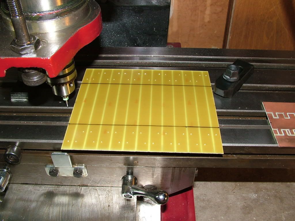
Non-copper side of capacitor board.
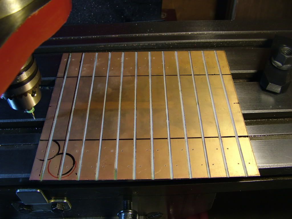
Copper side of capacitor board.
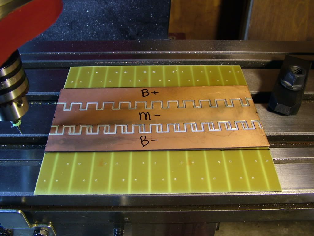
Mosfet/diode board on top of capacitor board, getting ready to drill holes for bus bars.
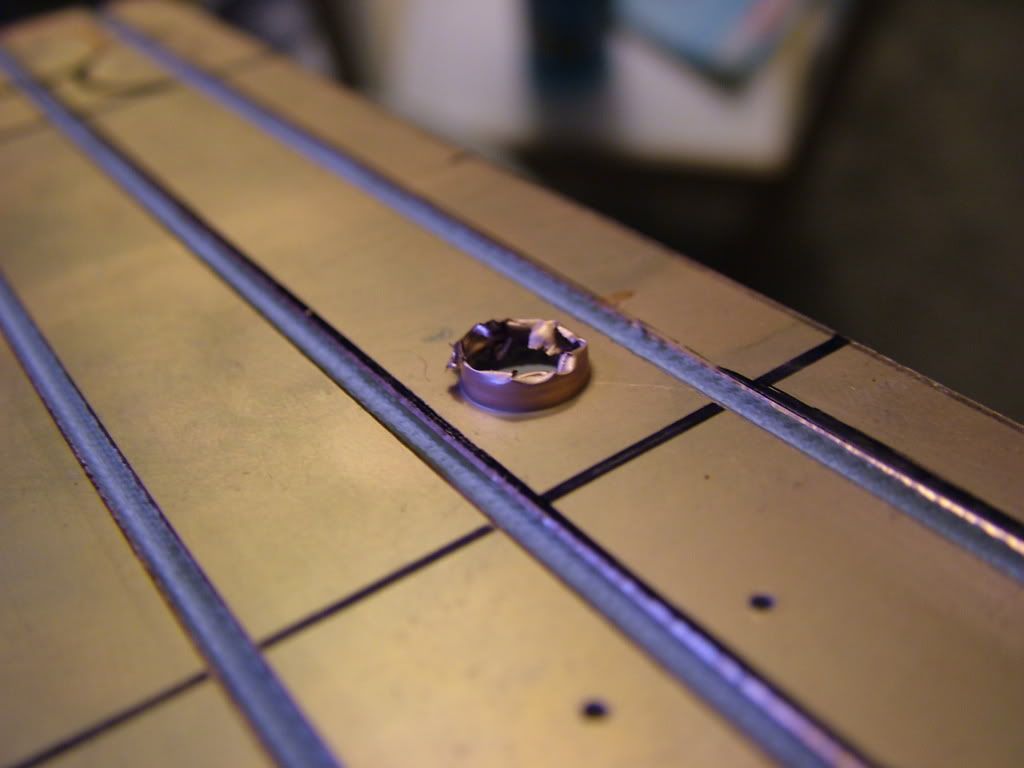
Oops, let's stop drilling, and make sure we only drill with copper on top, since evidently, copper gets sort of stretchy when it warms up.
|
|
|
|
|