Basically done with the power section (Only one more tiny thing).
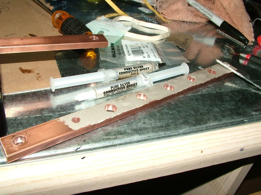
I can get about 15 more controllers out of the left over silver conductive epoxy (cold solder)! Ya! It doesn't take much.
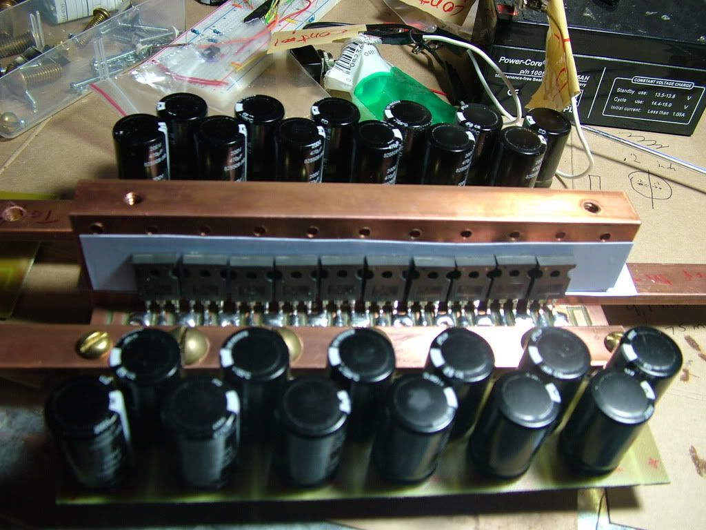
Part of the way done with the power section. One more bus bar to attach!
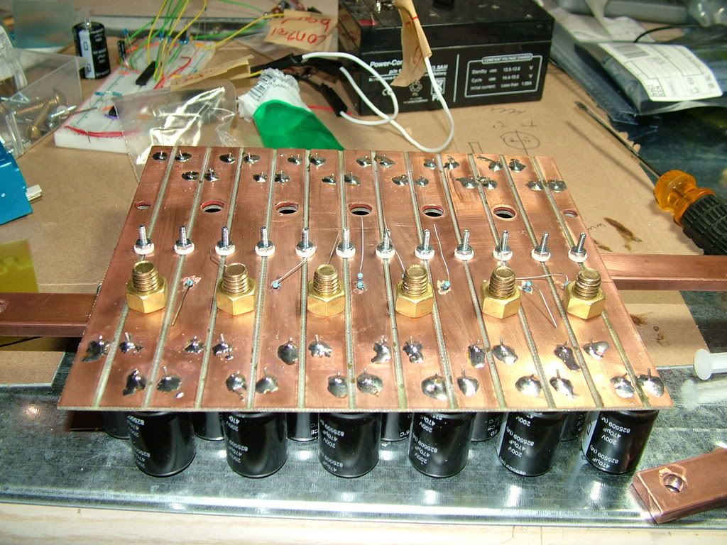
That blue thing is the current sensor!
Notice the backing of the mosfets/diodes, which electrically insulates them from the heat spreader.
Blah blah blah, more pictures.
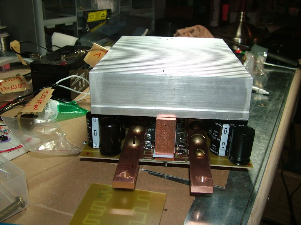
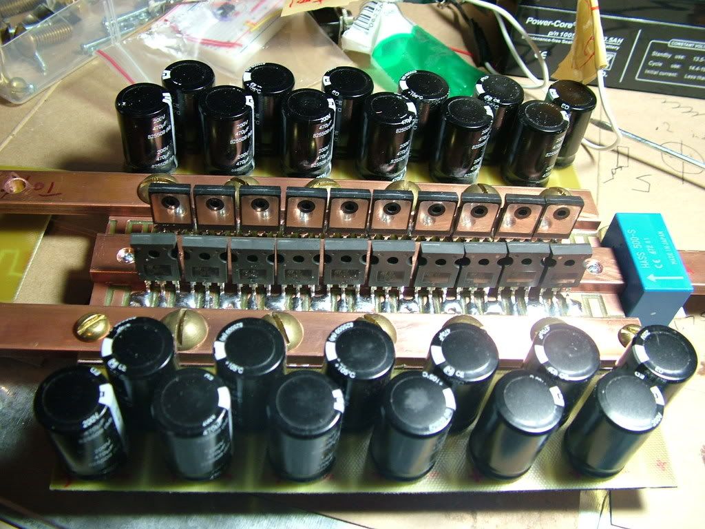
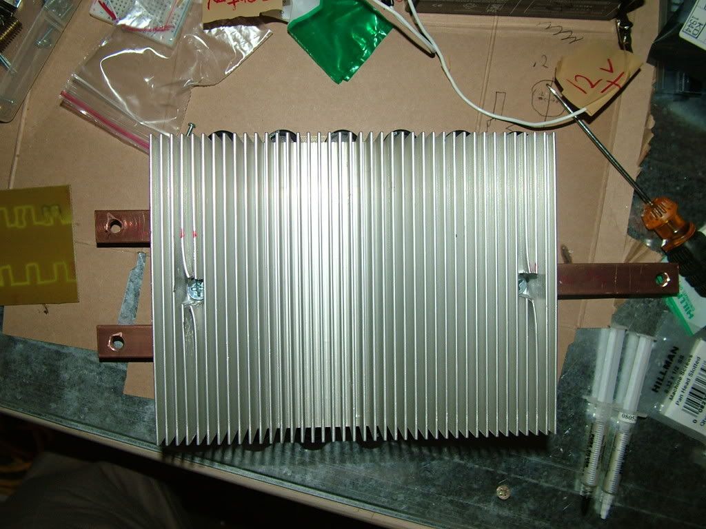
With Ben's heat sink! yaay!
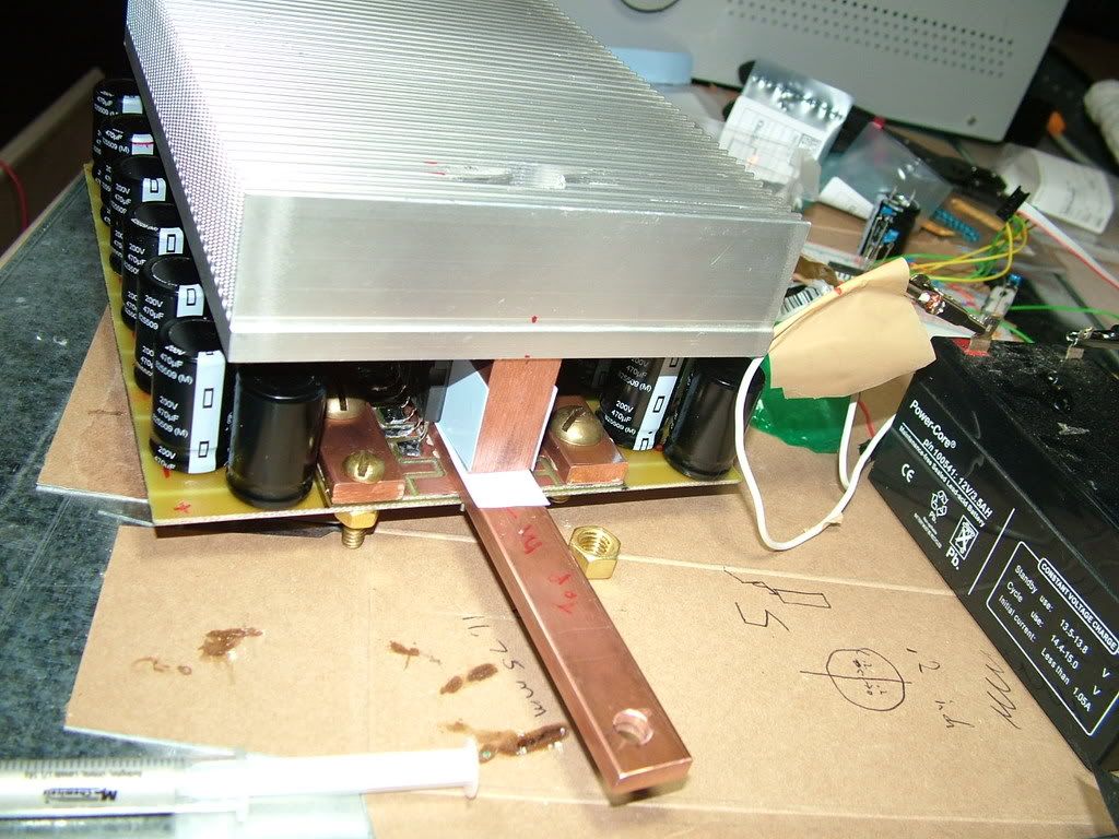
The M- side. Don't worry, after the box, only one inch of bus bar will be visible.
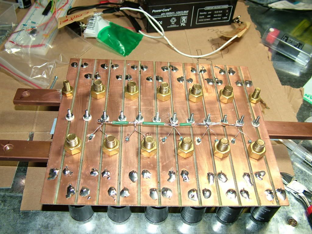
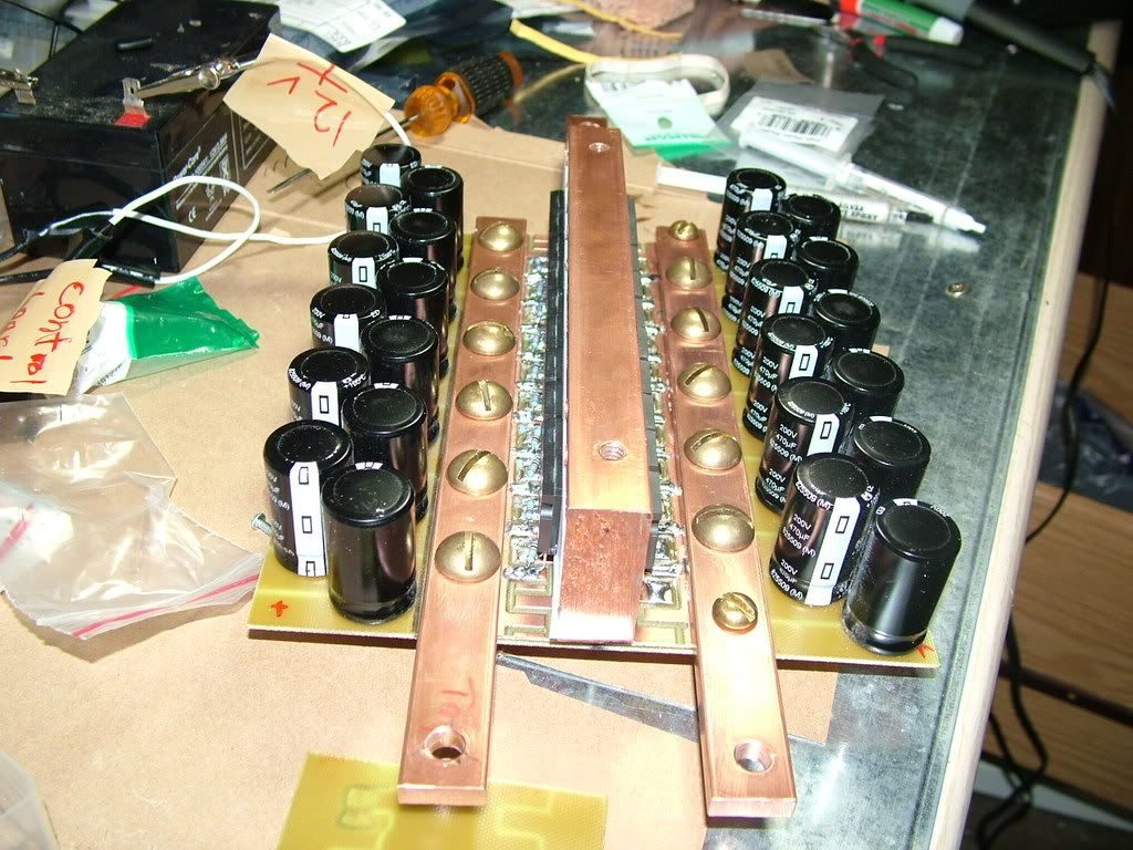
The capacitor side, with the gate resistors soldered. A single wire will connect the control board to the gate resistor string. Black box, anyone??? ya!
Sorry Ben.

slight mod necessary.


 Today
Today