 02-20-2012, 10:05 AM
|
#5491 (permalink)
|
|
Master EcoModder
Join Date: Apr 2009
Location: Charlton MA, USA
Posts: 463
Thanks: 31
Thanked 183 Times in 94 Posts
|
Quote:
Originally Posted by Weisheimer

That should be fun.
Which version of the control board are you using in your controller?
The machine looks like a blast, and your work looks good!
|
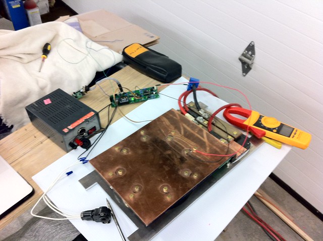
The controller is using Pauls 1kA control board. The original plan was to use my Uprising control board, but time was a limiting factor, so we just went with what he had already. I adapted it to work with the laminated bus power stage and tested it all out for him. The controller is using my driver board design.
Here is is during testing.
 Untitled
 by AdamBrunette, on Flickr
-Adam
|
|
|

|
|
The Following 3 Users Say Thank You to adamj12b For This Useful Post:
|
|
 Today Today
|
|
|
|
 Other popular topics in this forum...
|
|
|
|
 02-20-2012, 10:53 AM
|
#5492 (permalink)
|
|
Mark Weisheimer
Join Date: Aug 2009
Location: Columbus Ohio
Posts: 62
Thanks: 8
Thanked 13 Times in 10 Posts
|
Quote:
Originally Posted by adamj12b

The controller is using Pauls 1kA control board. The original plan was to use my Uprising control board, but time was a limiting factor, so we just went with what he had already. I adapted it to work with the laminated bus power stage and tested it all out for him. The controller is using my driver board design.
Here is is during testing.
 Untitled
 by AdamBrunette, on Flickr
-Adam |
Very nice work gentlemen!
I recognized the driver board in Isaac's photo link and of course Adam's
laminated bus.
It is grand to see it all together in such an exciting project!
I'm wishing you all the best of luck and fun in Michigan!
|
|
|

|
 02-20-2012, 01:00 PM
|
#5493 (permalink)
|
|
EcoModding Apprentice
Join Date: Feb 2010
Location: Northern Wisconsin
Posts: 137
Thanks: 32
Thanked 39 Times in 23 Posts
|
"we are both going to houghton michigan! we decided we might need him haha. he's taking monday off of work."
Wave when you go by me lol! I am near the border to "Yooper" land!

__________________
Dave  ...
|
|
|

|
 02-20-2012, 01:41 PM
|
#5494 (permalink)
|
|
Master EcoModder
Join Date: Nov 2008
Location: 18603, USA
Posts: 759
Thanks: 221
Thanked 60 Times in 45 Posts
|
Waugh! Been away too long! Paul - congrats on the wee one! You moved out of that basement you were living in yet?  I'll have to get a full catch-up here soon, any MAJOR changes I've missed? |
|
|

|
 02-20-2012, 02:27 PM
|
#5495 (permalink)
|
|
PaulH
Join Date: Feb 2008
Location: Maricopa, AZ (sort of. Actually outside of town)
Posts: 3,832
Thanks: 1,362
Thanked 1,202 Times in 765 Posts
|
No! We are broke again. Our daughter in Kenya finished 1st in her school of 300, and so she got to go to a fancy high school, which evidently isn't free over there. haha. And the girl she's living with finished 2nd, and you can't just leave her out in the 75 degree weather!
I'm putting together a 1000amp prototype, since the last one blew up. And I have an alternate high side design if this one blows up, and I'm also ALMOST done with an AC.
|
|
|

|
 02-20-2012, 02:50 PM
|
#5496 (permalink)
|
|
Master EcoModder
Join Date: Nov 2008
Location: 18603, USA
Posts: 759
Thanks: 221
Thanked 60 Times in 45 Posts
|
I know how that goes! Best of luck with everything! I'm still trying/waiting to get my 1000A IGBT version running myself - time, cold, and money all conspired against me.  |
|
|

|
 02-20-2012, 04:42 PM
|
#5497 (permalink)
|
|
EcoModding Apprentice
Join Date: Mar 2011
Location: alaska
Posts: 141
Thanks: 10
Thanked 37 Times in 19 Posts
|
Paul, I read somewhere you had designed a board with six isolated mosfet drivers onboard? I'm building a 9KW battery charger for a senior design class, and planning to use a full bridge converter with 4 mosfet switches. something with 4 isolated drivers would be awesome for this (:
|
|
|

|
 02-20-2012, 09:42 PM
|
#5498 (permalink)
|
|
PaulH
Join Date: Feb 2008
Location: Maricopa, AZ (sort of. Actually outside of town)
Posts: 3,832
Thanks: 1,362
Thanked 1,202 Times in 765 Posts
|
It's the gospel truth Miss Coates. (Old Yeller).
EDIT: If you want to use IGBTs, I did another one that takes 24v input instead of 15v, and outputs -8v up to 15v or something like that for the igbts to help them turn off better.
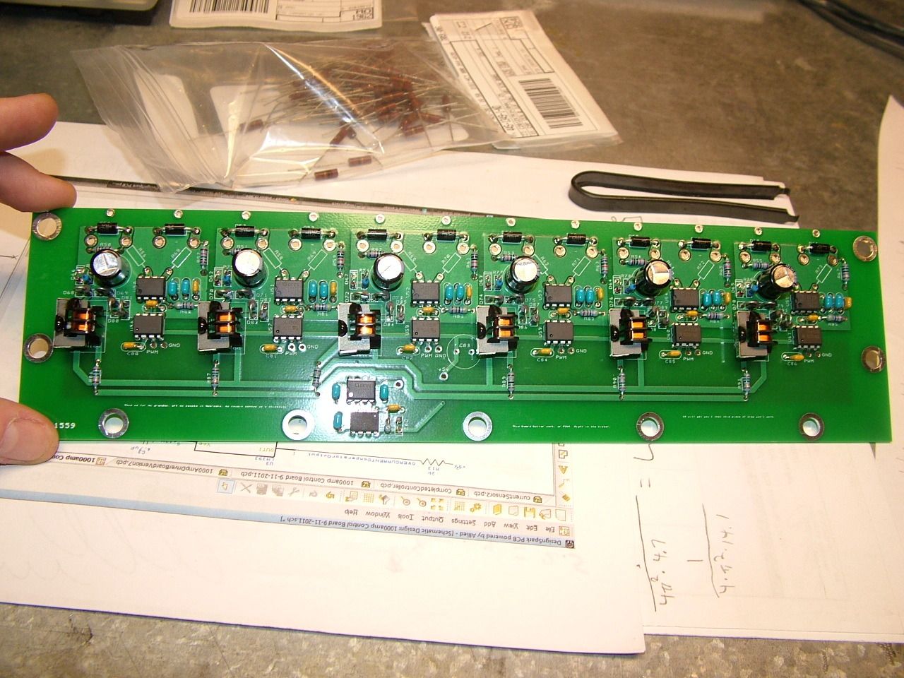
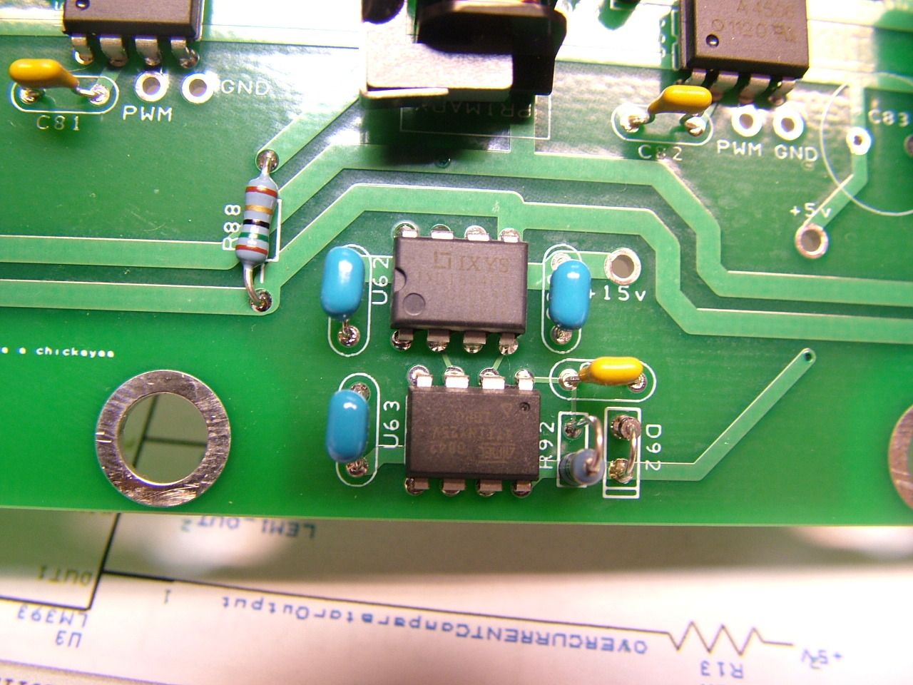
Here's a picture of it:

At the bottom is an ATTiny that is pulsing the 2 inputs of the dual driver at 70khz or so. When one is 0v, the other is 5v, and vice versa. That causes the output A of the mosfet driver to go high when output B is low, and vice versa. A push-pull converter or something like that.

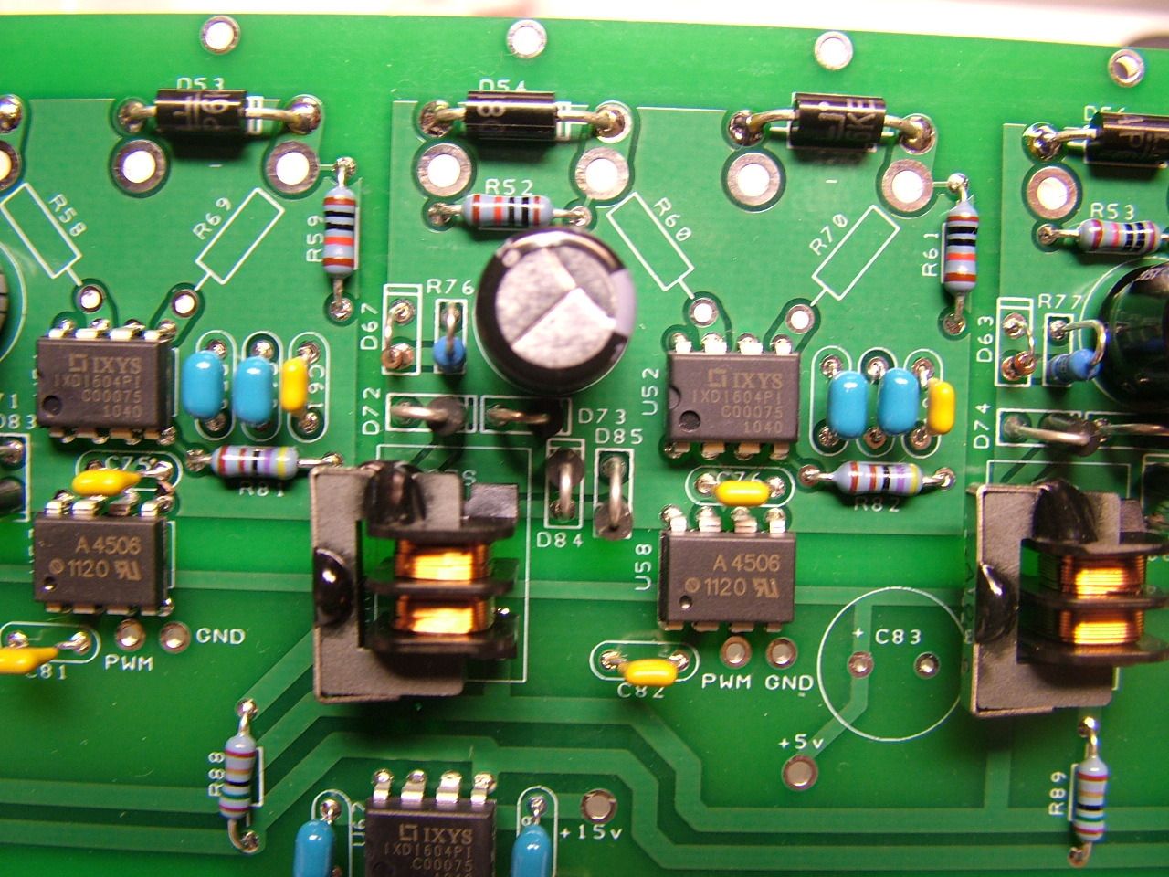
One of the 6 supplies. Notice D72,73,84,85 (Full wave rectifier). 6 hcpl-4506 optocouplers (u58 is one of them). 6 of ixdi604pi dual mosfet drivers (u52). One mosfet per driver output.:

Last edited by MPaulHolmes; 02-20-2012 at 09:55 PM..
|
|
|

|
|
The Following 2 Users Say Thank You to MPaulHolmes For This Useful Post:
|
|
 02-20-2012, 11:39 PM
|
#5499 (permalink)
|
|
EcoModding Apprentice
Join Date: Mar 2011
Location: alaska
Posts: 141
Thanks: 10
Thanked 37 Times in 19 Posts
|
that is awesome! very nice 
incidentally, we tested the board and controller at 200 volts today! even with no load on it, i can already tell it's WAY smoother than the old controller. with the old controller it was physically impossible to go slower than some certain speed...maybe 5 mph. no matter how slowly you eased into the throttle, at some certain point it would instantly accelerate to around 5mph. this one is touchy, but it won't accelerate any faster than you can punch the throttle. which is good!
also, the voltage sense leads to the board are tripping the isolation detector, so we have disconnected them, and adam says we can roll back the firmware so the contactor driver is on a timer instead of using voltage sensing. this thing is looking like it will rock REALLY AWESOMELY
Last edited by isaac_alaska; 02-21-2012 at 06:26 AM..
|
|
|

|
|
The Following User Says Thank You to isaac_alaska For This Useful Post:
|
|
 02-21-2012, 08:21 AM
|
#5500 (permalink)
|
|
ReVolt Enthusiast
Join Date: Jun 2009
Location: Michigan, USA
Posts: 239
Thanks: 97
Thanked 47 Times in 40 Posts
|
Quote:
Originally Posted by MPaulHolmes

At the bottom is an ATTiny that is pulsing the 2 inputs of the dual driver at 70khz or so. When one is 0v, the other is 5v, and vice versa. That causes the output A of the mosfet driver to go high when output B is low, and vice versa. A push-pull converter or something like that.
|
Hi Paul,
Your driver PCB is looking good!
Do you have any specs on those driver transformers you are using (turn ratio, inductance, isolation voltage)?
Also instead of using the ATTiny, why did you not just use an off the shelf Half Bridge Driver for a 50% duty-cycle? Example: (IR2085S).
Keep up the good work 
-Mark
Last edited by sawickm; 02-21-2012 at 11:03 AM..
|
|
|

|
|