 08-13-2014, 10:29 AM
|
#21 (permalink)
|
|
I got ideas
Join Date: Aug 2014
Location: Georgia, United States
Posts: 115
Beast - '97 Mercury Mountaineer
Thanks: 29
Thanked 23 Times in 15 Posts
|
Quote:
Originally Posted by aerohead

Automakers are being held to pedestrian safety legislation which is created to protect in a frontal collision.
The pedestrians body cannot deform the hood in an impact such that they strike a hard-point below (like the engine).
Cowl heights are being raised to allow for the crush zone mandated by the legislation.
The reason we don't see 'racing' cooling systems on passenger cars may have something to do with things which have nothing to do with efficiency.
|
I love it when that happens 
|
|
|

|
 Today Today
|
|
|
|
 Other popular topics in this forum...
|
|
|
|
|
08-13-2014, 11:12 AM
|
#22 (permalink)
|
|
...beats walking...
Join Date: Jul 2009
Location: .
Posts: 6,190
Thanks: 179
Thanked 1,525 Times in 1,126 Posts
|
Quote:
Originally Posted by Gasoline Fumes
|
Yep, it's a compromise between flow restriction vs. flow drag...with a minimized compromise typically ending up being the design-of-choice.
Last edited by gone-ot; 08-13-2014 at 09:54 PM..
|
|
|
|
|
The Following 3 Users Say Thank You to gone-ot For This Useful Post:
|
|
|
08-13-2014, 03:44 PM
|
#23 (permalink)
|
|
I got ideas
Join Date: Aug 2014
Location: Georgia, United States
Posts: 115
Beast - '97 Mercury Mountaineer
Thanks: 29
Thanked 23 Times in 15 Posts
|
Quote:
Originally Posted by freebeard
My suggestiontake a well-proven form like the Volkhart-Sagitta, use a boxer motor for that low hoodline and then put twin radiators in front of the wheels Boxter-style.
 |
Well I don't, nor do most people have, the ability to design a car from the ground up. That's great an all about the Volk and designing an optimal cooling system, but I'm talking about things we can do to the vehicles in existence... In our garages and driven every day 
Quote:
Originally Posted by freebeard
I'm with serialk11r. The difference between the P1 and the time attack cars is the former is organically curved (probably internally as well) while the latter look like an air conditioning duct. Easily fabricated but the un-filleted inside corners are not friendly to the air.
|
Quote:
Originally Posted by serialk11r
Okay I've attached an edited picture where I drew a red line around where I believe the "effective area" of the vents on the P1 is. I might be drawing it too big, they might have designed the edges of the vents in some tricky way.
|
I think they DID design it in some tricky way SerialK11r, and you're 100% correct freebeard when you state that the designs between the attack car and the P1 are different. Most if not all wind tunnel tested designs (that I see) have rounded edges within the ducting. There is a big difference between something made in a garage and something made in a factory with millions of dollars in RnD. But design specifics aside... Is the concept not sound? Surely we don't need a perfect design to see benefits from it's usage? I mean if it can get us a marked improvement, even if it's not as good as it could be, I would think it would be worth the time to consider and design it the best we can? Try to determine the optimal inlet/outlet ratio, hood placement, internal ducting design, etc etc. Figure out what *should* work for what we want to accomplish, so that anyone who wants to try it has some sort of starting point. I understand the EVO might not be what we want to replicate.... But would the mitsu from post #1 be more in line with our goals?
Quote:
Originally Posted by Gasoline Fumes
|
Thank you for this addition to the conversation!
Quote:
Originally Posted by serialk11r
Yes it's still huge, I'd say maybe about the same size as the one on the hood of the Corvette or the Evo. But look at a picture of the front of the P1.

The intake for that radiator is half the height of the nose, and extends nearly all the way to the headlights. My eyeball guesstimate is that the vent is maybe 30-40% bigger than the intake. Plus, the nose is raked down sharper than the front engined Vette or Evo, so the pressure there is higher in the first place.
The Evo has a puny intake that's half the size of that. There is no way enough air is making it to the other side of the radiator to be reducing lift. I bet the air in that vent is moving too slowly and is causing lift and drag. |
Again, the goals and system to which the rad duct partakes in, are different than they are for a supercar or ecomodder. But lets go with what you have brought up, inlet vs outlet size. Or rather lets start with inlet vs radiator size.
"We did some simple wind tunnel testing of a radiator with different size inlet ducts last year. Mass flow DOES increase with a smaller inlet vs radiator size (in our testing anyway and obviously only until separation begins)."
"Because the diverging duct increases pressure by slowing the air down, rather then slamming it against the radiator, which are basic pressure velocity fluid equations."
"A huge low pressure zone behind the wing and in front of the rad matches the low pressure behind it and cancels flow.
But then why wouldn't you just increase the bejesus out of your pressure in front of the radiator? I think you would, but not by using a huge converging scoop.
You want to increase your pressure in the area RIGHT in front of the radiator, not at the entrance of the duct. Say you have a CONVERGING duct. The pressure at the entrance will fall into equilibrium with the velocity pressure, like everyone has been saying. But then your pressure will decrease as the air moves towards the radiator. You will still have enough pressure and velocity to maintain flow through the radiator, and there will still be an even lower pressure behind the radiator. If you look at the pressure "continuum" throughout the process it will go from inlet=high, front of rad=mid, behind rad=low.
Ok, now use a diverging duct. The static pressure at the inlet will be atmo, the pressure right in front of the rad will be high, and the pressure behind the radiator will be low. So the pressure continuum goes: mid -> high -> low. The velocity pressure we have all been talking about will keep the flow moving forward through the mid -> high pressure region, aka the duct inlet to radiator. The optimal duct design will make the best use of this velocity pressure and flow the most air, more than a converging duct would. The highest pressure differential DIRECTLY across the radiator will produce the most flow (since the radiator is the restricting element). You need to find a balance however, between this pressure differential and the air velocity, to obtain the maximum mass flow rate. I believe the area ratio, A,rad/A,inlet, will be VERY close to 1, but less than 1.
If you go fast enough, like in a WWII fighter, the diverging-converging duct will actually produce thrust, like a mini pulsejet. However, in FSAE we cannot hope to go this fast, but the same flow-maximization concept applies."
"Also note the radiator core takes up space in the air stream so there may be a ~30% reduction in the actual area for air to flow through the core. Therefore a diverging-converging setup will help to keep airflow through the radiator at the same speed as the free stream air around it. This all seems to be a drag reduction exercise IMHO."
A really interesting read here, where I pulled these quotes from: Diverging/Converging Radiator Ducting - Why? These are small engine cars that see low speeds... No super cars, no time attack, just efficient design! ANd of course they design them from the ground up to do things we can't necessarily do with our vehicles (like converging duct exits behind the car. But there is a lot that can be learned from them.
So in a time attack or hill climb car where cooling is of the utmost importance, forcing more air mass through the radiator would be more important. And doing so in a manner which avoids extra frontal pressure and drag would also be important. The inlet for the EVO is smaller than the radiator for a reason, or so it would seem. They utilize the remaining leftover space for intake to the brakes, oil cooler, air intake for turbo. Remember, their goals are not the same as our goals... We don't have to cool red hot brakes and transmissions with our available front intake space.
See additional cooling intakes where the space for a converging intake scoop would normally be for the radiator. Also note the extreme thickness of the core the smaller intake is feeding... I understand the "duct" probably isn't long enough to create a true convergent pressure trait, but I think it abides by the same principle in the short amount of space it has to diverge towards the face. Like I said before, you guys are getting really hung up an example that is about as far from "normal" as we can possibly get 

Now lets talk about inlet vs outlet design, to see if your guess about the larger exit on the EVO is correct. Insight from the airplane crowd: Cooling
"Since the air is slowed before entering the radiator there is little necessity for streamlining the duct at the radiator. The fact that the air appears to have to make a right angle turn through the radiator in a horizontal layout does not cause problems...we are at this point working with pressure differentials not streamline high velocity flow.
Streamlining does come into play in the exit plenum/duct after the radiator. The "back" wall of the duct, the area into which the airflow exiting the back of the radiator will impinge should curve, gently or relatively abruptly but continuously towards the exit from the cowling. Sidewalls should also smoothly converge to the exit, meaning no square steps or direction changers, radiuses as gradual as possible but fitting the space available. You will hear rules of thumb that the exit openings, because the air is heated and thus presents more volume than the original intake air, should be 2.5 times the area of the intake opening. With good extraction of this heated air, allowed by the fact that it is exhausted into a low pressure area, the exit cross section can be as small as the intake in some cases (I believe this is the design of the P51 mustang right guys?). In others larger, but I have never seen this exit area have to exceed about 1.5 to twice the area of intake. Remember this air is compressing and accelerating producing a high flow rate."
You eyeballed the P1 and guessed 40% larger exit, so that would make sense for the car. Just as needing an even larger exit would make sense for a car with a MASSIVE cooling system creating what I would assume to be hotter than usual air exiting it like the EVO in question (like a prop driven airplane). I of course don't know any of this to be true. But given your example, and my examples, and the above reading material... It would make sense to me. I would also deduce that the thicker core is equivalent to a larger thinner core, there by giving the illusion that the exit ducting is far too large when compared to the cooling system and intake inlet. In reality it could be perfect given a higher rate of expansion due to heat exchange. But that is just speculation on my part.
Now with this 500lb gorilla in the room, downforce. As I have stated prior, the duct is part of a larger system which generates downforce. However, lets look more closely at the EVO's inlet/outlet ratio and then look even closer at the shape of the hood opening and duct work... Since we seem to be stuck on this idea.

You can see that the duct is as large or larger than the core... Then it actually converges, it becomes smaller before it widens again to meet the large opening of the hood. The pinched area of the duct looks to be about 1.5 times the inlet duct and maybe even closer to 1:1. This confines and speeds up the air as talked about by the airplane guys (right?), then it opens up bringing velocity down and creating a high(er) pressure zone like a rear diffuser or like the convergent inlet discussed above. Wouldn't this cause at least a small amount of down force? Again, I don't think this was designed for down force, but it's something you guys keep coming back to.
~C
|
|
|
|
|
08-13-2014, 07:37 PM
|
#24 (permalink)
|
|
Master EcoModder
Join Date: Aug 2012
Location: northwest of normal
Posts: 29,410
Thanks: 8,365
Thanked 9,125 Times in 7,534 Posts
|
Quote:
|
Well I don't, nor do most people have, the ability to design a car from the ground up. That's great an all about the Volk and designing an optimal cooling system, but I'm talking about things we can do to the vehicles in existence... In our garages and driven every day
|
I don't presume limitation on what you can build your garage. But using rear-engined cars as examples may be distracting. The closest I've seen to a Diable front end on a front-engined car is the Pontiac Pursuit concept.

It used an I4 laid on it's side, equivalent to a boxer-motor. Here is a thread you might find informative, discussing just moving the radiator to the back: http://ecomodder.com/forum/showthrea...ery-26356.html
Quote:
|
Again, I don't think this was designed for down force, but it's something you guys keep coming back to.
|
Not I.
|
|
|
|
|
08-13-2014, 08:05 PM
|
#25 (permalink)
|
|
EcoModding Lurker
Join Date: Jul 2014
Location: Laurel, MD
Posts: 44
Thanks: 1
Thanked 14 Times in 10 Posts
|
In case you haven't thought of this detail yet, one other thing to keep in mind with a duct outlet that points up is that rain will run down into the duct (especially when parked) so be sure to provide drains, and if you use electric fans they may have to be more waterproof than the typical radiator fan.
__________________
Regards,
Carl Ijames carl.ijames xx@xx verizon.net delete the xxs
|
|
|
|
|
The Following User Says Thank You to ijames For This Useful Post:
|
|
|
08-13-2014, 08:05 PM
|
#26 (permalink)
|
|
I got ideas
Join Date: Aug 2014
Location: Georgia, United States
Posts: 115
Beast - '97 Mercury Mountaineer
Thanks: 29
Thanked 23 Times in 15 Posts
|
Quote:
Originally Posted by freebeard
I don't presume limitation on what you can build your garage. But using rear-engined cars as examples may be distracting. The closest I've seen to a Diable front end on a front-engined car is the Pontiac Pursuit concept.
It used an I4 laid on it's side, equivalent to a boxer-motor. |
Kind of makes you wonder just what the big companies would be capable of if they actually tried huh? Stupid consumers and our tastes, and the stupid regulatory agencies and their red tape
I skimmed it, will give it a more thorough look tomorrow in my down time! I would also say that any placement which allows for the potential venting of gases/air in the rear of the vehicle is optimal is it not? It's merely the ducting that's the nightmare on many cars right? I'm not trying to advocate that radiator hood ducting is the end all be all... Just seems like if we could figure out a starting point from an eco, rather than performance standpoint, it would be accessible to those who wanted to give it a go. I have zero engine bay room on my truck, or I would try it myself just for ****s and giggles ") Although I don't see my flat hood and razor thin "break over" point being anywhere near optimal for this 
Touche, my apologies.
~C
|
|
|
|
|
08-13-2014, 08:17 PM
|
#27 (permalink)
|
|
I got ideas
Join Date: Aug 2014
Location: Georgia, United States
Posts: 115
Beast - '97 Mercury Mountaineer
Thanks: 29
Thanked 23 Times in 15 Posts
|
Quote:
Originally Posted by ijames
In case you haven't thought of this detail yet, one other thing to keep in mind with a duct outlet that points up is that rain will run down into the duct (especially when parked) so be sure to provide drains, and if you use electric fans they may have to be more waterproof than the typical radiator fan.
|
I had thought about it, hadn't figured out an answer (yet).
The fans I see used in these are slimline sealed units with electrical wires run through a bung in the back/bottom of the duct after the radiator. I haven't looked too hard into their ability to survive rain/weather... I had initially wondered/worried about snow and foreign objects. As far as water pooling up, if you tilted your radiator just a smidge to the front, the water could drain out into the front ducting and maintain a relatively small puddle that I assume would be ejected the minute you got some air coming through the duct. But if I'm not mistaken, some land speed guys set their core in a box of water to assist with cooling in the absence of appropriate airflow... Of course I'm sure these aren't your average radiators and inter-coolers though!
Just add this to the list of things to figure out
~C |
|
|
|
|
08-13-2014, 11:08 PM
|
#28 (permalink)
|
|
EcoModding Lurker
Join Date: Jul 2014
Location: Laurel, MD
Posts: 44
Thanks: 1
Thanked 14 Times in 10 Posts
|
Hmm, your plan is to vent up towards the front of the hood, right? That means when you say "get some forward motion and the water will be ejected", doesn't that mean it will all land on the windshield? I think you should put a couple of hose barb fittings in the lowest corners, and then underneath attach short pieces of tubing that extend down to level with the bottom of the frame so the water goes down under the car. Something like 1/4" ID tubing won't pass enough air to disrupt your airflow, I wouldn't think. You could also put window screen over the outlet to stop debris from entering, and if it snowed the snow should build up on the screen mesh instead of going through and filling the duct. Yes, it restricts the airflow but it keeps stuff out.
__________________
Regards,
Carl Ijames carl.ijames xx@xx verizon.net delete the xxs
|
|
|
|
|
08-14-2014, 12:33 AM
|
#29 (permalink)
|
|
Master EcoModder
Join Date: Jan 2012
Location: United States
Posts: 1,756
Thanks: 104
Thanked 407 Times in 312 Posts
|
Chillsworld,
Now that I think about it the area that I drew is probably wrong.
Everything I have said has been about efficiently ducting air through the radiator. I think the time attack cars have exhausts that are too big because the air that goes in has to go out, and I don't think there are any large pressure differentials on a car that can account for serious compression/expansion of the air.
Whatever location you want to exhaust the radiator, you want to match the velocity of the exhaust stream with the air going around the car. The full opening in the hood is not a cross section of the flow in a good design because if the air were traveling straight up you'd get some serious turbulence there.
That however doesn't really change the argument; taking this into account, it's now plausible that the P1's "effective" opening is around the 115% NACA figure (which is also a reasonable amount for the air to be expanding due to heat). If you are to have any chance of matching the velocity, you have to match the speed of the flow first, and the inlet to outlet ratio + the temperature increase across the radiator is what determines the ratio of the speed of the flow going into the inlet and leaving the outlet.
With those time attack cars then, there are a couple possible problems (in my amateur eyes):
1. The rectangular exit is not the appropriate shape because air doesn't flow straight over the hood, a lot of it "spills" to the sides, and you'll get some vorticity or something like that at the edges.
2. The radiator is nicely ducted and the air may be attached along the duct, but the inlet is WAY smaller than the outlet, and the radiator is not going to heat the air up enough to let it leave at a high enough velocity. This would create lift, although it would probably increase flow through the radiator. My guess is that it's better to enlarge the inlet and match the outlet rather than blindly enlarge the outlet.
|
|
|
|
|
08-15-2014, 01:18 AM
|
#30 (permalink)
|
|
Lots of Questions
Join Date: Jan 2013
Location: San Jose
Posts: 665
Thanks: 343
Thanked 101 Times in 79 Posts
|
Found this pic of the Mclaren P1 radiator/internals. Notice the awesome angle that Mclaren puts the radiator at, just like what Figure 'C' of the image Gasoline Fumes posted!!!
Also notice the "LTR Ducts" that Mclaren added to just in front of the wheels just before production?! Apparently they aid in cooling and extra down force.
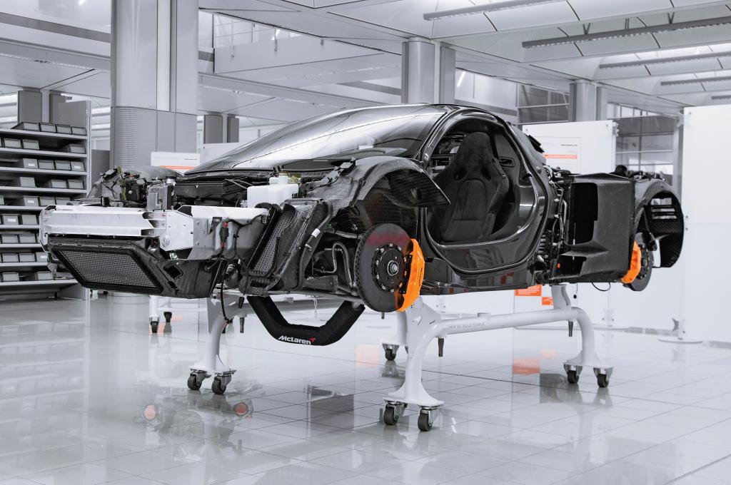
P.S. Liking where this thread is going, wasn't sure where it was headed in the beginning, but now it's making me want to cut up my hood and put a big gaping hole in it! 
__________________
Don't forget to like our Facebook page!


Best EM Quotes:
Quote:
Originally Posted by aerohead
It has been said, that if you peel the duct tape back on Earth's equator, you'll find that the two hemispheres are held together with J B Weld.
|
Quote:
Originally Posted by Dan9
subscribed with a soda.
|
Quote:
Originally Posted by aerohead
If you're burning,and someone throws gasoline on you,there will be a localized cooling effect, but you're still on fire.
|
|
|
|
|
|


