 02-20-2016, 04:42 PM
|
#11 (permalink)
|
|
Master EcoModder
Join Date: Aug 2012
Location: northwest of normal
Posts: 29,096
Thanks: 8,259
Thanked 9,021 Times in 7,454 Posts
|
The designs you show are thoughtful. The first one should be very stable, it's used on land-speed record cars. The second one I've seen called a catamaran design. That was the first thing I thought of when it sounded like the question was 'what's the perfect single number for all cases everywhen'. The third is my least favored.
It looks like you've been thinking about that mandated hole in the top, with some drainage channels at the back. In some ways it more important than the bottom, being more tightly regulated. What would you think of an everted NACA duct for the leading edge of the opening? Or just adding a half-circle to the rectangle with a plexigalss windscreen. Angle the sides up past the driver's eye level like a F1 race car?
How do you find the NURBs modeling? Is there a tool path to get you to a cutting pattern? I like polygon modelers because you can pick dimensions off even non-contiguous vertexes/vertices.
Here is something to tie it all together: aerohead's example (just implemented as a three-wheeler) in a polygon modeler (just blown up to motor-home size*). It's completely malleable on the X-, Y- and Z-coordinates, to fit your need.
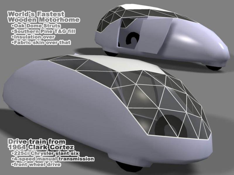
*I should update the graphics since the motor home donor vehicle is gone. Think Tesla Model S drivetrain.
|
|
|

|
 Today Today
|
|
|
|
 Other popular topics in this forum...
|
|
|
|
|
02-23-2016, 09:03 PM
|
#12 (permalink)
|
|
EcoModding Lurker
Join Date: Feb 2016
Location: Cornwall, UK
Posts: 18
Thanks: 5
Thanked 11 Times in 7 Posts
|
Tried a few models of having 1 or 2 naca duct or have the top surface slope down as much as possible. However any of these don't reduce the drag much as they disturb the air earlier, causing more turbulence. The only solution that might help is the last one, which slopes down as much as possible without interfering me getting out of the car in emergencies. This reduces the low pressure in the cockpit opening.


I like the second design better than the first as it will most likely be easier to manufacture especially for the mounting for the rear wheels compared to the first one. But I have concerns about the airflow under the car as it might churn up and cause large amount of drag or it might keep its laminar flow??
I don't use NURBS surface modeling for my models, I use Solidworks CAD software to make all of the bodies including the chassis component and so on. I could export the body shape into another software for flattening but to be honest the body is all compound curves to keep the airflow attached. The second body design will consist of two parts, plus a nose cone and am planning to make simple moulds for it. |
|
|
|
|
02-24-2016, 06:46 AM
|
#13 (permalink)
|
|
Master EcoModder
Join Date: Aug 2012
Location: northwest of normal
Posts: 29,096
Thanks: 8,259
Thanked 9,021 Times in 7,454 Posts
|
Second and first from Permalink #9? The catamaran body shouldn't churn the air if it's smoothly finished. It may have problems with increase surface area in crosswinds. Note that aerohead's example and my third one use a 'wingtip' pointed downward to enclose the wheel.
Have you compared raising the cockpit edge toward the rear, rather than the drainage channels on the sides of the headrest. It seems like that would bleed turbulence rather than slicing it off.
Solidworks uses splines, see https://en.wikipedia.org/wiki/Non-un...ional_B-spline. It is a parametric solid modeler as compared to a direct polygon modeler. Why Use NURBS for Surface Modeling...? suggests that Solidworks is needlessly complex for what you are trying to do, compared to say Rhino 3D or Maya. But, use what you have. |
|
|
|
|
02-24-2016, 06:23 PM
|
#14 (permalink)
|
|
Master EcoModder
Join Date: Jan 2008
Location: Sanger,Texas,U.S.A.
Posts: 16,437
Thanks: 24,483
Thanked 7,412 Times in 4,802 Posts
|
cockpit
Would the rule book allow something like an elastic Lycra Spandex panel to enclose this cockpit area ,which Velco's onto your helmet leading edge below the visor ?
In an emergency egress situation it would simply shear away at the velcro attachment points as soon as you moved appreciably.
It WOULD be aeroelastic and probably 'shudder' a bit,but would be better than that enormous void which cannot support any kind of airflow.
__________________
Photobucket album: http://s1271.photobucket.com/albums/jj622/aerohead2/
|
|
|
|
|
02-24-2016, 06:40 PM
|
#15 (permalink)
|
|
EcoModding Lurker
Join Date: Feb 2016
Location: Cornwall, UK
Posts: 18
Thanks: 5
Thanked 11 Times in 7 Posts
|
Freebeard - What do you mean by raising the sides of the cockpit so it bleeds turbulence? Unfortunately, I can't have any bodywork above the eye level except the front wheel fairings and mirrors, its one of the rules. So at the moment I'm only peeking over. I have also included a picture of my previous car with the 1st body and the 2nd body I made for it and as you can see, I can only just see over the top.
Aerohead - Unfortunately, it wouldn't be legal, it has to be a permanent cockpit opening. Would have a fully enclosed driver if I had my choice.


I made two different style bodies for my previous car, one with 30mm of ground clearance, 16" wheels with full fairings around them. That one also had a long nose and a chopped off backend.
I wanted to improve the performance, so I decided to modify the chassis so the ground clearance is 85mm, as well as using smaller 14" wheels. I also reduced the nose to the minimum 200mm and made the back end tapered. Both of the bodies came to the same ballpark of performance and therefore I don't have a real idea of which approach to make for the new bodywork. Your opinions?
I also did more testing of having the channel vs no channel, and it showed a significant difference, about 25% increase in the drag when there's no channel (although it would be less than this in reality) because when the airflow trips over, it has a effect on the size of the wake behind the car. It also reduces the pressure in front of the helmet as you can't see the green area in front of helmet. So will definitely be having this feature.

Yeah, I have been using Solidworks for a long time and am used to it. Also been using a Solidworks built-in flow software for the recent tests, and has been giving much more useful and consistent results. |
|
|
|
|
02-25-2016, 04:19 AM
|
#16 (permalink)
|
|
Master EcoModder
Join Date: Aug 2012
Location: northwest of normal
Posts: 29,096
Thanks: 8,259
Thanked 9,021 Times in 7,454 Posts
|
So that answers the question about the cockpit opening. The sight-line requirements and CDF analysis point the way. Bringing the fairing forward to cover the back of the helmet looks like a good move if the rules allow it.
What materials did you use on the two previous iterations? The beveled sides on the first one look like they would provide a little more front wheel clearance. Did the blunt nose and longer tail show any improvement?
|
|
|
|
|
02-25-2016, 05:17 PM
|
#17 (permalink)
|
|
Master EcoModder
Join Date: Jan 2008
Location: Sanger,Texas,U.S.A.
Posts: 16,437
Thanks: 24,483
Thanked 7,412 Times in 4,802 Posts
|
opinion
Just thinking out loud:
*consider a 2-D streamline form to minimize frontal area
*do the 30mm clearance at the front axle
*do the 100mm clearance at the rear
*this offset will allow you to use the entire under body as a drag reducing diffuser (no downforce).
*place the batteries just above the belly where you can to keep the C.G. low for roll stability.
*rake the body with low front/high tail.This will help keep the upper airflow attacking the body all the way to the canopy,where the flow will be compromised by the opening.
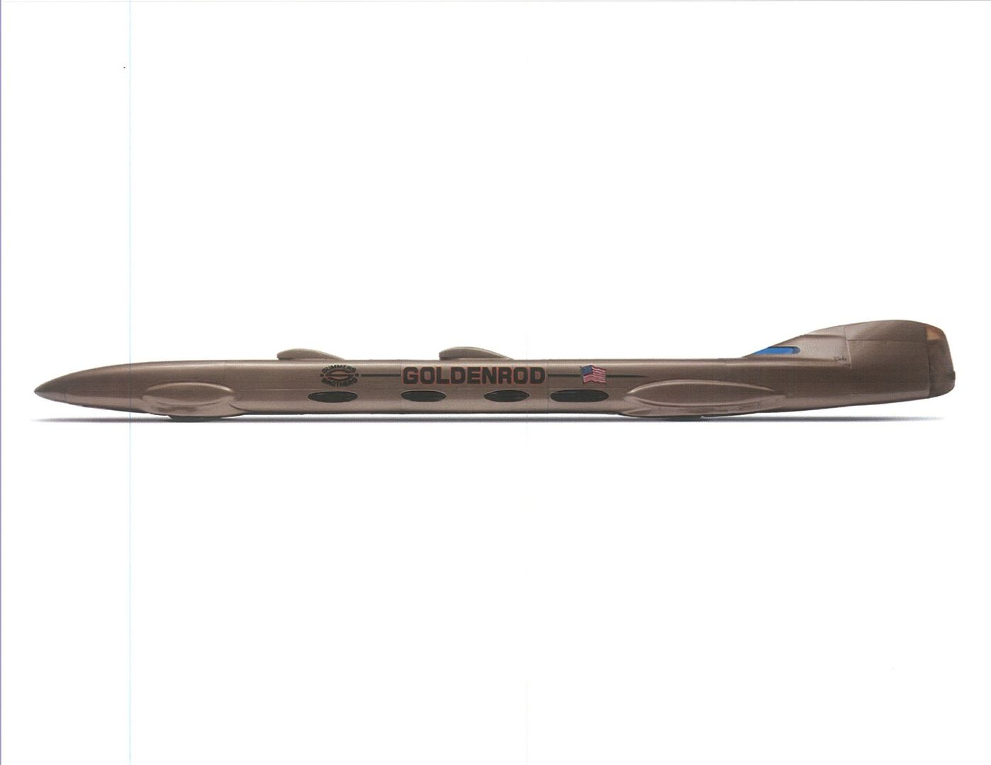
*place the canopy as far forward as you can to use whatever is left of the 2,800mm to streamline behind your head,like this Summers Brother's Goldenrod
*try to fully integrate your helmet as a bulbous leading edge to the fairing.
*integrating the roll bar into this rear fairing will help the flow to recover from the open canopy turbulence.
*if you can't get the roll bar inside the fairing,then streamline the tubing as best you can and blend it into the top of the shell to kill hook vortice formation.
*put your 500mm wheel track in the rear
*design the wider front track to agree with the streamline contour
*Fully enclosing the wheels,even though it adds frontal area,completely offsets the interference drag of 'open' wheels.
__________________
Photobucket album: http://s1271.photobucket.com/albums/jj622/aerohead2/
|
|
|
|
|
02-25-2016, 07:55 PM
|
#18 (permalink)
|
|
EcoModding Lurker
Join Date: Feb 2016
Location: Cornwall, UK
Posts: 18
Thanks: 5
Thanked 11 Times in 7 Posts
|
I used corroflute, which is a very light plastic material and used Polyproplene hot glue to fasten the panels together on the inside and a strip of electrical tape.
The bezels are for reducing the frontal area as much as possible as corroflute is a flat sheet material and can't be formed into compound curves and therefore I used three sections on the side as shown below. By the way all of the wheels are cambered 10 degrees inward.

Aerodynamically, yes it was a better body with much better rear aero as it tapers to a point. However other factors such as increased in car weight, and dying batteries meant that it performed about the same as the first version.
Aerohead - Thanks for the ideas, there's a lot of restrictions in the rules that prevents some of the ideas you're mentioning, I will try to rattle through them, a lot of them I have tried to implement into my design.
The 2D side profile of my best body so far is similar to a streamline shape as you can see below, just stretched out. It's slight cambered towards the front to minimise the squashing of the airflow at front of the car.

This has a 95mm ground clearance at the middle and towards the front and increases up to 150-170mm at the backm, so similar increase to what you're saying. I'm not sure I was clear before but the 100mm ground clear only applies to the batteries base height and the driver's bottom. Everything else can be much higher so there is some flexibility there.
The top surface does keep increasing in height until the canopy, same as you suggested. Also the head fairing is as faired as much as possible. 
The roll bar has to be exposed because there is a line is drawn from the front roll bar to the rear, there must be 50mm of clearance between the line and my helmet. Also recently, they banned any fairing for the top 150mm of the rollbar, the other teams weren't very happy at all about that.
The plan is both the front and rear track to be at the minimum of 500mm plus all wheels have a 8-10 degrees negative camber to reduce the frontal area even more. The frontal area is about 0.225m^2 or less, about 10 times smaller than an average car.
I did some flow simulations on the three designs I posted on here, I did them on the more accurate Solidworks software and it gave me some surprising results. The 3 wheeler even though it has completely tapered rear end, the amount of surface area made it a lot worse, about 40% higher drag force than the second design. So I would agree with you with that completely enclosed wheels are the way to go.
Also if you're interested to know, the third design (the catamaran design with the side flanges cut off) I posted in permalink #9 has about 15% more drag force than the second design. The channel underneath and the side flanges is definitely helping out reducing the drag. |
|
|
|
|
The Following User Says Thank You to stealth For This Useful Post:
|
|
|
02-26-2016, 12:30 AM
|
#19 (permalink)
|
|
Master EcoModder
Join Date: Aug 2012
Location: northwest of normal
Posts: 29,096
Thanks: 8,259
Thanked 9,021 Times in 7,454 Posts
|
For work with corroflute (I assume like coroplast) that looks really good. The slab sided one was probably less work? Nice surface finish though—is that like coroplast with an aluminum skin?
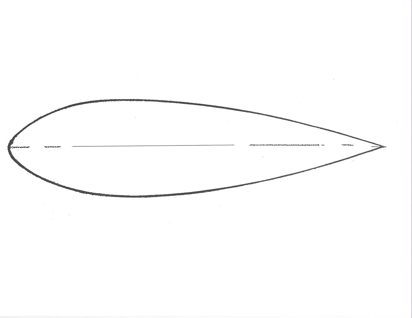
The teardrop aerohead posted is ideal, then there's those rules. The teardrop has maximum width at 30% of the length. You can truncate the last 10%, a Phantom tail. The rear axle could be at 60% plus or minus, with reduced track the further back it is.
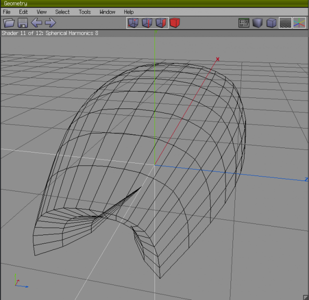
This shows a flat floor with a half-exponential horn replacing the flat rear truncation. It provides space for the rear wheels. |
|
|
|
|
The Following User Says Thank You to freebeard For This Useful Post:
|
|
|
02-26-2016, 04:36 PM
|
#20 (permalink)
|
|
Master EcoModder
Join Date: Jan 2008
Location: Sanger,Texas,U.S.A.
Posts: 16,437
Thanks: 24,483
Thanked 7,412 Times in 4,802 Posts
|
catamaran
I'm not surprised about the catamaran.HONDA tested one for the 1993 World Solar Challenge and it came in Cd 0.15 (if my memory serves me) vs Cd 0.10 for the 'pumpkin seed'/ flattened-torpedo (as Goro Tamai refers to them) shape that they ultimately used in competition.And won. 
__________________
Photobucket album: http://s1271.photobucket.com/albums/jj622/aerohead2/
|
|
|
|
|


