 02-18-2016, 07:44 PM
|
#1 (permalink)
|
|
EcoModding Lurker
Join Date: Feb 2016
Location: Cornwall, UK
Posts: 18
Thanks: 5
Thanked 11 Times in 7 Posts
|
Underfloor and Body design of Greenpower Car (similar to Electrathon)
Hello all, new here.
I'm currently designing a Greenpower car and would like to know which type of underfloor and ground clearance would be best for low drag. I don't know whether this is a good place to ask but since it's eco, electric and focused on aero, I'll try here.
Some information on a Greenpower car, it is essentially a extremely small single seater electric car and we enter into races with other student built cars. We have the same batteries and motor and therefore we have to design the most efficient car possibly to go as fast and far as possible in a hour race. Aerodynamics is the biggest factor which is why I want to get it right.
( http://www.greenpower.co.uk)
Fastest cars tend to go at 40mph + which all of my CFD testing is at. The racing is done on large tracks so only minimal steering angle is required.
We are given a set of rules and regulations that we have to comply with and the couple mains one are:
Minimum 500mm track, 4 wheels are required.
Maximum 2800mm length, 1200mm height and width
Only 14" - 20" bicycle wheels are allowed.
Must have a open cockpit opening of 350mm wide and 600mm long.
Ground clearance can't be any less than 30mm.
The bottom of the driver and batteries can't be higher than 100mm off the ground for roll safety.
Finally, it has to fit me (6ft) in the car.
If you are interested, you can have a look at this link which has many of Greenpower cars examples.
http://www.flickr.com/photos/querth/...h/21880485434/
Two most recent winners - See the difference in ground clearance and FA
http://www.facebook.com/GreenpowerRa...type=3&theater
With that out of the way, I have spent hundreds of hours designing a wide variety of bodies and testing it in a CFD software called Autodesk Flow Design. This doesn't however include any moving road simulation which is important for seeing what effect the ground clearance has on airflow underneath and behind the car. I was wondering if any of you guys would have any idea of what would be better in reality.
What would be better, 30mm of ground clearance which reduces the turbulence underneath the car but increases frontal area and makes it more difficult to taper the body at the rear without destroying the underflow,
or
95mm of ground clearance (maximum), which reduces frontal area which is relatively small already but have more turbulence underneath which can cause more drag and air spilling from underneath.
Would be interested to hear what your opinion is.
Last edited by MetroMPG; 03-04-2016 at 12:31 PM..
Reason: (fixed links, added to title)
|
|
|

|
 Today Today
|
|
|
|
 Other popular topics in this forum...
|
|
|
|
 02-18-2016, 11:40 PM
|
#2 (permalink)
|
|
Master EcoModder
Join Date: Jul 2011
Location: Ann Arbor, Michigan
Posts: 4,210
Thanks: 140
Thanked 2,824 Times in 1,981 Posts
|
Quote:
Originally Posted by stealth

If you are interested, you can have a look at this link which has many of Greenpower cars examples.
wwwflickrcom/photos/querth/albums/72157659968306378/with/21880485434/
|
The link to the gravity racers is not working, let's try this again.
https://www.flickr.com/photos/querth...7637777375534/
Right one?
The biggest difference between those gravity racer examples and ones favored in this forum is the outboard wheels (there) verses a monolithic body enclosing the wheels (here).
EDIT: Let's test that Facebook link too.
https://www.facebook.com/GreenpowerRacing
Correct?
__________________
George
Architect, Artist and Designer of Objects
2012 Infiniti G37X Coupe
1977 Porsche 911s Targa
1998 Chevy S-10 Pick-Up truck
1989 Scat II HP Hovercraft
You cannot sell aerodynamics in a can............
Last edited by kach22i; 02-18-2016 at 11:59 PM..
|
|
|

|
|
The Following User Says Thank You to kach22i For This Useful Post:
|
|
 02-19-2016, 03:12 PM
|
#4 (permalink)
|
|
Master EcoModder
Join Date: Aug 2012
Location: northwest of normal
Posts: 29,340
Thanks: 8,346
Thanked 9,110 Times in 7,523 Posts
|
It depends.  Firstly, this is the sort of question that is of interest here, but...
Quote:
|
I have spent hundreds of hours designing a wide variety of bodies and testing it in a CFD software called Autodesk Flow Design.
|
...maybe you should be schooling us.
Questions:
Are you competing in Goblin, 24 or 24+ class (I hit 6ft when I was 14)?
This standard motor and two batteries—where do they go?
The ~14x24" rule for the cockpit opening how is that measured?
What fabrication skills and tools do you have a available?
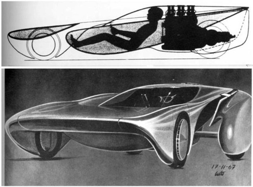
Here are three contrarian shots in the dark. First Luigi Colani:

The body is flat on top and curved on the bottom: free downforce. Minimal body/ground interference drag. This car ran at Bonneville Salt Flats.
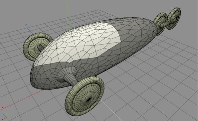
Secondly, my own design I would like to run at Bonneville someday:

The four-wheel layout mimics the Speed Demon. It may or may not be allowed under your sanctioning body's rules.
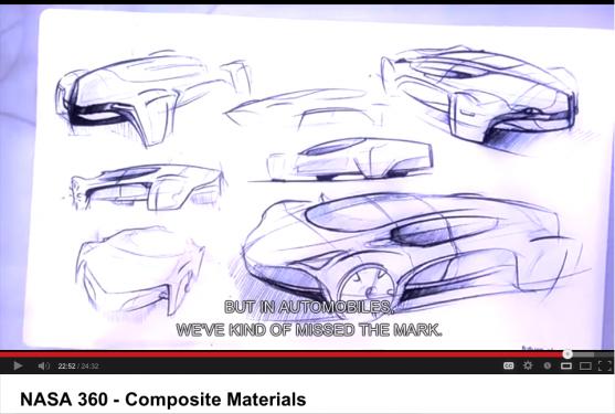
Thirdly, a screenshot from a Youtube video which I believe represents an early iteration of the Edison2:

Last edited by freebeard; 02-19-2016 at 03:20 PM..
|
|
|

|
 02-19-2016, 07:07 PM
|
#5 (permalink)
|
|
EcoModding Lurker
Join Date: Feb 2016
Location: Cornwall, UK
Posts: 18
Thanks: 5
Thanked 11 Times in 7 Posts
|
Yeah, well the hours spent is really just messing around with a variety of shapes, but with no definite answers which leaves me with no real idea of what is the ideal ground clearance and plus the software is nowhere near accurate enough to give me useful results, only useful for showing pressure areas and rough idea of the turbulence behind the car.
I'm competing in the F24+, which has the exact same technical regulations as F24 but we have shorter races with the same energy available and therefore its faster.
All of the car run with the 24V electric motor in the rear although nothing in the rules says it can't be front wheel drive but this is a complex and heavy system. The 2 x 12 V car batteries can be placed anywhere in the car as along they are 100mm or less off the ground, some cars have them in front of the feet, behind the helmet or one on each side of the driver. It all depends on the body.
Bearing in mind, the car is much smaller than a standard car, the electric motor is only 100mm in diameter and 200mm long. Some of the smallest and fastest cars only measure about 400mm high, and 570mm wide and 2.8m long and this would be including the wheels.
This is the rule on cockpit opening.
T7.4. The cockpit opening, when viewed from directly above must be able to accommodate a rectangle 600 mm in length and 350 mm wide with no intrusions, e.g. helmet fairings, instrument covers, etc. must not overhang this area. The driversí helmet must be positioned at the rearmost point possible of the cockpit, creating a clear space in front of the driversí helmet.
In terms of fabrications method and tools, the car will be mostly handmade, will probably make some moulds to form the body which might turn into a monocoque. Im open to anything, its only concept at this stage. The body design ideally should be simple so that the time spent in the manufacturing is reduced greatly. Also a possibility of some parts like jig panels etc being CNC routed locally, but will cost more.
For this kind of competition, we don't need any lift or downforce at all, all focussed on getting the lowest drag possible and I kind of think if there is any downforce or lift being exerted on the car, it's using up energy from trying to moving the car around.
I would love to do that almost three wheeler design, but the rules states that there must be 4 wheels, 500mm minimum wheel track and must be symmetric along the centreline.
I will try post some pictures of some of body designs I have come up with.
|
|
|

|
 02-19-2016, 10:43 PM
|
#6 (permalink)
|
|
Master EcoModder
Join Date: Aug 2012
Location: northwest of normal
Posts: 29,340
Thanks: 8,346
Thanked 9,110 Times in 7,523 Posts
|
This sounds similar to the Electrathon racers that compete locally. Those are limited by battery weight, not number. What are the battery dimensions?
Electrathon racers tend to have stiff, if any, suspension and a thin noisy body that rattles as they go by. I would consider Polymetal. It is stiff and would make for a rigid moncoque, but would favor simple curved surfaces.
The 'almost three-wheeler' design could be built with 4 wheels, even enclosed. The rules sound like they would permit a narrow rear track, like an Isetta. The basis is that the body can be constructed from triangles, diamonds or hexagons. Each edge is mathematically defined to whatever precision you can cut to. If it's flattened into a 'peel pattern' it could be cut out of a flat sheet with the darts cut as overlapping tabs that are riveted or spot welded. Sort of a quasi-compound curve.
I will now wait quietly for your pictures.
|
|
|

|
 02-19-2016, 11:35 PM
|
#7 (permalink)
|
|
EcoModding Lurker
Join Date: Feb 2016
Location: Cornwall, UK
Posts: 18
Thanks: 5
Thanked 11 Times in 7 Posts
|
Interesting, never heard of Electrathon before, but looking at it, it's quite similar to Greenpower here in the UK. They have very similar design and rules as we have. Only thing is that they can have three wheelers, so much better than four wheels for efficiency, can only wish that we had that rule  Going to spend some time researching into some of their cars.
We have two batteries that are supplied by Greenpower and they are 36Ah batteries, (195L 130W 165H) |
|
|

|
 02-19-2016, 11:43 PM
|
#8 (permalink)
|
|
EcoModding Lurker
Join Date: Feb 2016
Location: Cornwall, UK
Posts: 18
Thanks: 5
Thanked 11 Times in 7 Posts
|
Yes, if the body was quite simple, I could use that method for the car, however I think in terms of body designs I have been working on, I was thinking more on the lines of strip planking which has been used for kayak building i think, will allow me to make consistent smooth curves on the edges to prevent air spilling and causing drag. Also the body needs to be really smooth to keep the boundary layer close to the surface as possible to minimise drag.
Now have 5 posts which means I'm allowed to post pictures, coming soon.
|
|
|

|
 02-20-2016, 12:14 AM
|
#9 (permalink)
|
|
EcoModding Lurker
Join Date: Feb 2016
Location: Cornwall, UK
Posts: 18
Thanks: 5
Thanked 11 Times in 7 Posts
|

This one is a front wheels in, rear wheels out. Main idea was to taper the rear completely so it's a smooth flow. However there is additional drag from the exposed wheel fairings. This has 100mm of ground clearance which is maximum.


This one has what I call a "channel" underneath the car, as the wheels have to have fairing, I just used the whole side of the car as a fairing which massively reduce the air spilling underneath. The top of the channel is 100mm off the ground but the side parts are only 30mm off the ground. However the question I was using this thread for was how does the ground clearance affect the flow underneath, does it stall it and cause chaos. This design depends on that alot. This has been producing the similar drag levels to the first one despite having more frontal area.

Another one, high off the ground, all wheels in. As the air go through the wheels underneath the car, it tends to expand and cause more turbulence behind the car, but this has the minimal frontal area.
|
|
|

|
 02-20-2016, 12:41 PM
|
#10 (permalink)
|
|
Master EcoModder
Join Date: Jan 2008
Location: Sanger,Texas,U.S.A.
Posts: 16,506
Thanks: 24,517
Thanked 7,436 Times in 4,817 Posts
|
design
I would have you consider the 1993 Team New England TNE-II design.It would have won the North American Solar Challenge had it not been for cloudy weather.It was faster than the 'winner' by far.Cd 0.10 and low projected frontal area,plus very stable in cornering.
https://en.wikipedia.org/wiki/Team_New_England
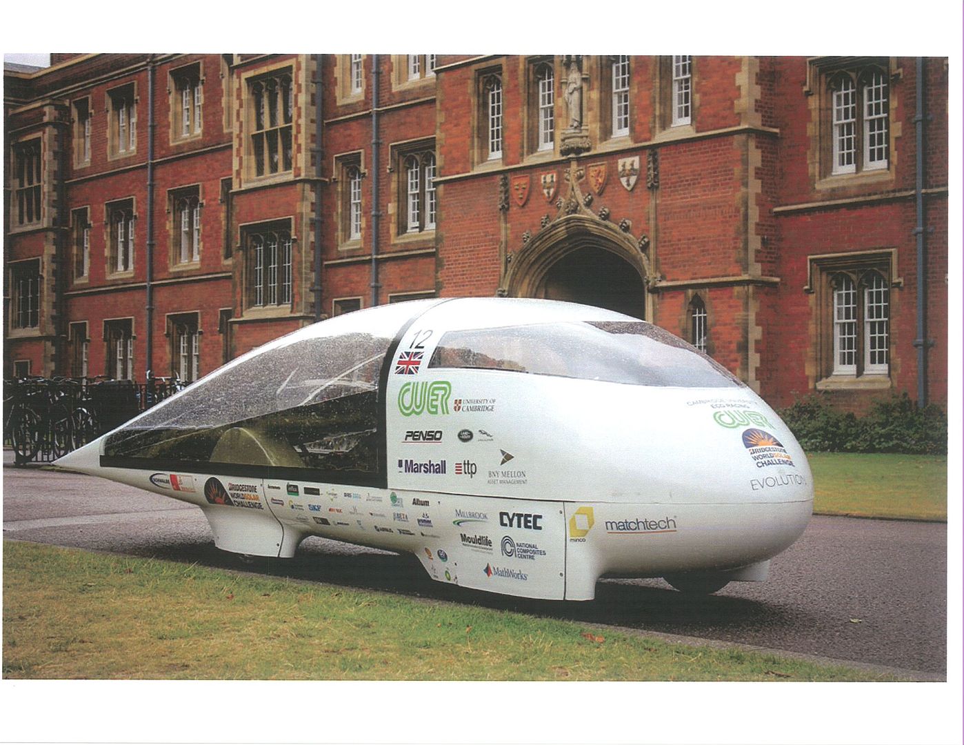
Also,the 2013 Cambridge University CUER solar racer,Cd 0.10,and even lower projected frontal area and surface area.

Laminar boundary layer shapes are going to look great in the wind tunnel and CFD,depending upon Reynolds number,but in a real race environment,it will be impossible to attain a laminar boundary layer flow due to Earth's turbulent boundary in which you'll be racing.
__________________
Photobucket album: http://s1271.photobucket.com/albums/jj622/aerohead2/
|
|
|

|
|