02-26-2016, 03:57 PM
|
#21 (permalink)
|
|
Master EcoModder
Join Date: Jan 2008
Location: Sanger,Texas,U.S.A.
Posts: 16,534
Thanks: 24,520
Thanked 7,438 Times in 4,818 Posts
|
roll bar
It's a shame about the exposed roll bar.It will have premature laminar boundary layer separation.
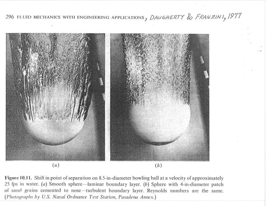
Would the rule book allow some sort of dimples,trip wire, or micro-vortex generators on the tubing?
I know it's kind of splitting hairs,but the interference drag from the tubing loop will be disproportionately large,especially since it's in the aft-body area,compromising the head fairing.
During World War-II,the directional hoop antennas on Allied,Luftwaffe,and even Japanese Imperial aircraft were often enclosed within streamlined housings to cut drag and extend flight range.
__________________
Photobucket album: http://s1271.photobucket.com/albums/jj622/aerohead2/
Last edited by aerohead; 02-26-2016 at 04:00 PM..
Reason: add image
|
|
|

|
 Today Today
|
|
|
|
 Other popular topics in this forum...
|
|
|
|
|
02-28-2016, 08:17 PM
|
#22 (permalink)
|
|
EcoModding Lurker
Join Date: Feb 2016
Location: Cornwall, UK
Posts: 18
Thanks: 5
Thanked 11 Times in 7 Posts
|
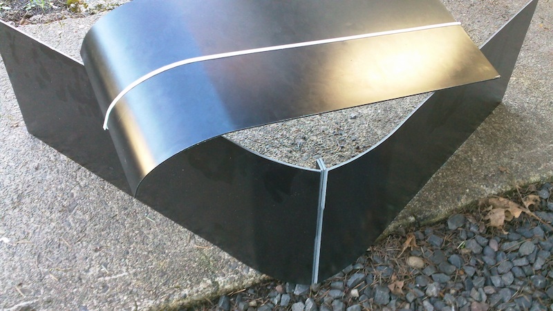
Freebeard - Thanks, it's just coroplast, no aluminium skin or anything, it's a light material although difficult to shape. The second body was much easier, all done by hand, where as the first one, I had to make a jig to lay up the panels in and glue it all up.
I wasn't sure which ground clearance you were thinking of so I tried both 30mm and 100mm models. The inverted horn shape at the back does help to reduce drag quite a bit. The 100mm model gave me a slightly lower drag than the 30mm model but only by 3% despite having a much larger frontal area. Both model were about 15-17% less drag than catamaran design in permalink #9. Here's some pictures of what I did.


After this I went back to the catamaran design as I wasn't happy with the front section as I felt it was too abrupt to the airflow. I moved beginning of the side flanges much further back and rounded the front nose off as much as possible. I also made top two edges along the body to have a much bigger radius to allow the airflow to flow more easily around the corners. This gave me the lowest drag force so far, about 22% less than the original catamaran body and a drag coefficient of 0.11. I'm going to have do tests on the most of the models at 15% yaw as airflow is never going to hit the car dead on with crosswind and so on.
Aerohead - Unfortunately there's not much I can do on the rollbar, the only thing I can do is, there's been a trend lately to hide the rollbar behind the helmet to minimise the impact of it by having a very small bend radius, like I had on my previous car.
All of the rules of Greenpower can be found here, there's a section on roll bars, banning the use of fairings - http://www.greenpower.co.uk/sites/de...ons%202016.pdf |
|
|
|
|
The Following User Says Thank You to stealth For This Useful Post:
|
|
|
02-29-2016, 01:18 AM
|
#23 (permalink)
|
|
EcoModding Lurker
Join Date: Jan 2016
Location: -
Posts: 28
Thanks: 9
Thanked 11 Times in 11 Posts
|
No dimples on the roll bar...would a very rough paintjob help?
|
|
|
|
|
02-29-2016, 01:04 PM
|
#24 (permalink)
|
|
Master EcoModder
Join Date: Aug 2012
Location: northwest of normal
Posts: 29,422
Thanks: 8,369
Thanked 9,128 Times in 7,537 Posts
|
Thanks for that. I've had some predictions verified before, but this is the first time someone has confirmed a suggestion I've made, so this is a big deal to me. 
I know that you can't expect absolute Cd values from your software, but just for my bragging rights, could you close off the horn with a flat truncation and see how much difference is made there? TIA
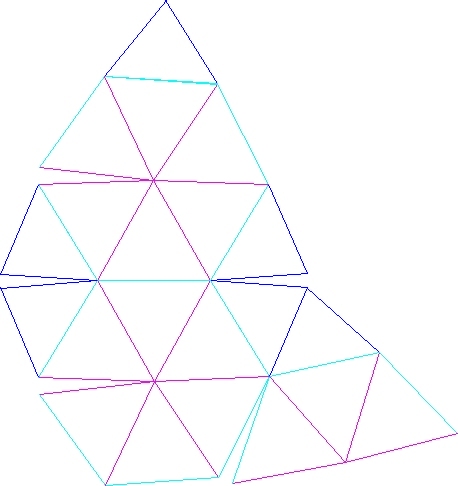
Coroplast, if you hadn't noticed, is popular here. It's light and inexpensive. There is a triple-wall variety. The open-wheel racer I posted in Permalink #4 is based on a 4-sided pyramid, shrunk on one diagonal and stretched on the other. It has had a geodesic subdivision applied, in this case 6v or a frequency of six. At 2v it is very angular, like an F-117. Someday I would like to compare 2 through 6v in a wind tunnel. Anyway...
The point being that it is all flat surfaces, be they triangles, diamonds, hexagons or a mixture. If you take a big sheet of coroplast you could cut reliefs on the inner edges and darts on the perimeter to fold a geodesic shape. Here is a (spherical) example from Google:
 https://www.google.com/search?q=geodesic+peel+pattern
Here is something I prepared for another thread showing an edge treatment for coroplast. Un-edged on the left, wrapped with tape in the center, and double folded and wrapped on the right.

Less inexpensive but more permament is Polymetal. I've worked with samples of it:
Compared with 5/8th inch plywood, it is about as stiff, 1/10th the weight and twice the cost.
Check the rule book for perforated base plate. Applied to your roll bar it would be like teeth of a comb diminishing in size behind the roll bar uprights, but not touching it. I doubt a strip of sandpaper on the front would do much in the turbulence coming off the helmet. But you could wear a feather boa or inflated HANS device to fill up the opening you can't put a tonneau cover over.
Edit: Here's another example, using hexagons:
 http://thecookinmama.com/category/diy/
They didn't make V-cuts, or just wide cuts, so it's folded the wrong way. With an ellipsoid, the relief cuts on the inner surface will be wider in the pointy ends than in the middle. Due to the dihedral angles.
Last edited by freebeard; 02-29-2016 at 04:39 PM..
|
|
|
|
|
The Following User Says Thank You to freebeard For This Useful Post:
|
|
|
03-01-2016, 04:56 PM
|
#25 (permalink)
|
|
EcoModding Lurker
Join Date: Feb 2016
Location: Cornwall, UK
Posts: 18
Thanks: 5
Thanked 11 Times in 7 Posts
|
I had a look at removing the inverted horn, and it had odd effects on the drag figures. The front section has not been changed at all. On the model that has 100mm of ground clearance, flat base, removing the inverted horn increased the drag from 5.4N to 5.9N, increase of almost 10%. The pictures shows that without the airflow that going through the horn and pushing up the wake, it allows the airflow from the top go down and push aside all of the other airflow.


However what's interesting is that for the 30mm ground clearance, the drag values are near identical. I think this is because of the size of the horn and the low ground clearance makes for a rapid expansion of the airflow which has similar drag level to having a solid back end.

It all depends on the size of the horn and the ground clearance but I think it can be used to reduce the drag if done correctly. In terms of the Cd accuracy, in terms of real world predictions, the software wouldn't be any good unless I can get some real world validation, but it's accurate and consistent for when comparing designs and their drag values.
The two rules on rollbar aerodynamics:
Aluminium or steel square or circular section roll bars are to be used and must be strong enough and of sufficient dimensions to perform satisfactorily - Means that I can't use aero profile tubing.
The top 150 mm of the roll bar must not have any fairing or other aerodynamic aid - Not really specific as I could have a fairing behind it that's mounted on the body but not attached or touching the rollbar. Kind of against the spirit of the rules but is a possible loophole so it's possible to have a plate behind it. Plus I'm only having the minimum 150mm exposed to the airflow.
Thanks for the info on the different methods. Although it would be easier to make, any sharp edges will make the air trip over and I need to make sure that the airflow stays laminar as possible for long as possible for the best performance. If I was to make another body out of corroflute, I would make it like my first body and use thin long strips and have multiple chamfers for the corners. Also incorporate the foam/fibreglass nose of the second one.
But I think I will make a fibreglass/carbonfibre bodywork that is smooth and curvy. Just need to make sure the body shape is right . |
|
|
|
|
The Following 3 Users Say Thank You to stealth For This Useful Post:
|
|
|
03-01-2016, 06:30 PM
|
#26 (permalink)
|
|
Master EcoModder
Join Date: Aug 2012
Location: northwest of normal
Posts: 29,422
Thanks: 8,369
Thanked 9,128 Times in 7,537 Posts
|
Thanks for taking that extra step. I bookmarked you post. I understand that varying parameters, more than just ground clearance (straight vs exponential horn, etc.) could optimize the result. And that it's for comparison purposes only. I'll take 10% as the significant number. It's not really my idea, it came from a rectangular duct under a drift racer or something.
I mapped out how I would tackle coroplast FWIW. I'm a fan of formless construction. If you make a wide slot in the flutes and backside it would result in a radius. The ones going laterally are the problem, so you lay out with diamonds. Chain them together and the result is a long strip with non-parallel edges.
That first body you built could be rendered as a triangulated low-poly model. I don't know much about the tool path from the Solidworks model to a cutting pattern.
If your thinking fibreglass/carbonfibre bodywork, look into http://basalt.guru. It's a competitive product. You could for instance layer a fiberglass skin with a basalt mesh reinforcing backing, the thermal expansion is the same.
Last edited by freebeard; 03-01-2016 at 06:40 PM..
|
|
|
|
|
03-02-2016, 09:17 PM
|
#27 (permalink)
|
|
EcoModding Lurker
Join Date: Feb 2016
Location: Cornwall, UK
Posts: 18
Thanks: 5
Thanked 11 Times in 7 Posts
|
For that first body, I exported that model into a paper folding software called Pepakura and once I got the pattern which wasn't perfect, had a quite a few broken panels, I had to modify it in Draftsight, and used that to cut the big corroflute sheets.
If I'm doing a body similar to the catamaran design, I think I would use the underside of the body as part of the chassis which is a very wide upside down 'U' shape and use a laminate structure to form the backbone of the chassis. The front 200-300mm will be a foam structure for the crash protection. The whole top and side surfaces of the body will be a single piece of carbon fibre or fibreglass shell with minor reinforcement. All depends on time as always 
The channel underneath makes it useful for making the chassis stiffer but I have to make sure that having a channel underneath is good thing, the tests tells me that it helps a lot for having really low drag. If I remove the side flanges of it, it tends to increase the drag (10%) by exposing the more of the wheels and as the wheels are static in the virtual wind tunnel, the effect would be greater when the tiny wheels are actually spinning around at 40mph. This is usually minimised by using wheel fairings underneath.
So its a case of whether having 4 individual wheel fairings (smallest FA) or two long sweeping fairings like the catamaran design (slightly bigger FA) or completely lowering the ground clearance down to 30mm and reduce the draggy underflow (biggest FA). What would your choice be? |
|
|
|
|
03-03-2016, 02:17 AM
|
#28 (permalink)
|
|
Master EcoModder
Join Date: Aug 2012
Location: northwest of normal
Posts: 29,422
Thanks: 8,369
Thanked 9,128 Times in 7,537 Posts
|
A flat floor that has a stiffening longitudinal corrugation that begins toward the front, is wide and flat under the driver seat and then begins an exponential flare to the truncation of the aeroform. Cross pieces between the tunnel and the catamaran section for seat mounts.
Maybe a flat, or at least lower, floor between the front wheels with half-catamarans that grow out of that to enclose the rear wheels?
At some point packaging the drivetrain and suspension on that floorpan is all beyond me.
|
|
|
|
|
03-03-2016, 02:19 AM
|
#29 (permalink)
|
|
EcoModding Apprentice
Join Date: May 2008
Location: N. Saskatchewan, CA
Posts: 1,805
Thanks: 91
Thanked 460 Times in 328 Posts
|
I just noticed this thread in my monthly mail. Bravo, and apologies for lateness/duplication.
While the air under the car is certainly in shear, a popular way to get around the lack of a moving ground plane is to simply mirror the shape and observe the gap between the two "bottoms." An ideal shape in free air, when brought close to its twin, will distort progressively so that the two adjacent surfaces become flat as they touch, leaving no visible seam as they merge into one body of the original shape but double volume.
The exposed wheel bottoms add frontal area, but enough ground clearance for easy street use is good, because it can better handle the inevitable imprecision. Wheel exposures benefit from fairing, but make sure to align it with the local airflow, not just the wheel itself. Use smooth wheels and wheelwells, with minimal gaps at the openings. Detailing matters quite a bit. Don't let air leak from one pressure zone to another through the interior, except through planned, tapered ducts.
For your cockpit, you want to create a stable, attached vortex to produce a virtual roof. Some decent examples can be found in the LeMans sports classes from the 60s, before the lads discovered downforce. Draw a shape that has a fairly flat roof the shape of your cockpit opening, and then just cut a hole. The ideal shape for the cavity is very rounded for easy, fast circulation, blended to a rounded rear edge that won't catch air, and is lowered enough to account for the growth in the boundary layer. Anything you can do to feed high-velocity air to the start of the gap will help reduce turbulence. There isn't much in the literature, but I could maybe scan what I have if there's interest.
Exposed roll bars are very nasty. Just strategic roughness helps if it has to stay round, but even a crude cardboard or foam fairing taped on can hardly miss at halving the drag. Good ones can reduce it by an order of magnitude.
The softer the ride, the less momentum lost on each bump, and the lighter the tires you can use. You can achieve suspension just by controlling the flex in the frame. The most basic improvement would be to have the batteries and/or seat on springboards. With more travel comes more potential troubles about keeping things perfectly aligned and not scrubbing, but it is easy to make big gains. It is pretty easy to design A-arms that replace the hinge with a wide quarter-elliptic spring, and then blend in to the rest of the structure without heavy transitions. I have articles on full suspension from frame flex, and on Coroplast fairing construction linked at The Car Cycle
Re: Selection of materials, from among those popular in the field.
Choose the ones you enjoy working with, and have the tools/facilities for. You can machine aluminum with carbide woodworking equipment. The exotics are wasted if you don't have craftsmanship. Honeycomb panels can be handy and light. For a one-off, I'm partial to using a lot of wood, and with epoxy encapsulation it can be excellent structurally, but the coating must be protected from even small nicks where water can enter, and from UV light. A thin layer of fiberglass gives good mechanical protection, and will tie together many wooden members. |
|
|
|
|
The Following User Says Thank You to Bicycle Bob For This Useful Post:
|
|
|
03-03-2016, 03:46 AM
|
#30 (permalink)
|
|
EcoModding Lurker
Join Date: Nov 2008
Location: Bristol, UK
Posts: 22
Thanks: 0
Thanked 4 Times in 2 Posts
|
Hey there, veteran F24 and F24+ racer (and national podium winner) here, so I should be able to give some insight. Our team gallery is here if you want to see some more photos, including construction galleries. https://picasaweb.google.com/thepodmovement/

Our F24+ car. I understand the rules have changed somewhat from when we raced, but it should give some inspiration. The batteries lived behind those removable front wheel panels.

Our (slightly left field) F24 car, designed as such because I was too tall to fit in a car with the batteries in a somewhat aerodynamic place, so we put them outboard to halve the frontal area vs putting one either side. I ended up outgrowing this car too and getting a pass to move on to F24+ early (I was the reason F24+ cars are allowed to be longer, heh).
The chassis design for both is semi-monocoque. Welded steel frame (old school tables with the chewing gum peeled off) with components bolted to it, but not strong enough to support the car on its own. The rest of the strength is provided by bamboo and plywood, held together with fiberglass. Incredibly stiff, and I actually completely wrote off (accidentally! They cut me up) a honeycomb aluminium and carbon fibre F24+ car in the F24 car (for a while we raced it in both formulae) with barely a scratch.
Note the design cues: an upwards taper on the rear end and high ground clearance: we wanted to get as much of the car way from turbulent air near the ground as possible. We also used cheap and available materials; steel, bamboo, plywood, household filler. In our minds the expense of high end composites, TIG welded aluminium (which we would have had to have outsourced - not our M.O) weren't worth it, we thought we could (and did) beat teams which depended on expensive materials through better design and driving. Seriously, driver training is a huge factor. Did you know that you don't have to brake into the chicane at Goodwood?
Any more specific questions feel free to ask, now that I'm not involved any more I'm happy to share trade secrets with other teams 
__________________


|
|
|
|
|
The Following 3 Users Say Thank You to Joe of Loath For This Useful Post:
|
|
|