11-03-2014, 02:16 PM
|
#41 (permalink)
|
|
EcoModding Lurker
Join Date: Sep 2013
Location: Ontario
Posts: 6
Thanks: 5
Thanked 0 Times in 0 Posts
|
Thanks Bob,
What did you use to attach the aluminum covering, self tapping metal screws? What wall thickness tubing and angle did you use?
Thanks so much again, the flickr album helped immensely. I think I am going to go for something very similar to your design except a little less beefy as my bed is not as long as yours and to try and keep the weight down and thus $ down.
|
|
|

|
 Today Today
|
|
|
|
 Other popular topics in this forum...
|
|
|
|
|
11-03-2014, 04:35 PM
|
#42 (permalink)
|
|
Diesel Trucker
Join Date: Apr 2012
Location: Aspers, PA
Posts: 35
JD - '04 Dodge Ram 2500 QCLB 4x4 SLT Last 3: 18.93 mpg (US)
Thanks: 17
Thanked 22 Times in 13 Posts
|
Quote:
Originally Posted by bmack2

Thanks Bob,
What did you use to attach the aluminum covering, self tapping metal screws? What wall thickness tubing and angle did you use?
Thanks so much again, the flickr album helped immensely. I think I am going to go for something very similar to your design except a little less beefy as my bed is not as long as yours and to try and keep the weight down and thus $ down.
|
Aluminum rivets to attach the aluminum sheet, I'm going to replace with SSteel one of these days. all the 1" tube is 1/8" wall everything else is 3/16" wall. the only steel is 2"x6" rect. tube., 3" x3" angle and 1"x1" square for the top. couple pieces of plate 6" x6" to cap the ends of the top horizontal bar.
__________________
Bob,
Dodge Ram '04.5, 2500 HO, Auto, QCLB, 4x4, CAI, 4" turbo back, Smarty Jr, Airdog 100. So Far
Previous; Dodge Ram '03, 3500, QCLB, 4x4, Dually, RIP
|
|
|
|
|
The Following User Says Thank You to rdefayette For This Useful Post:
|
|
|
11-03-2014, 09:38 PM
|
#43 (permalink)
|
|
Aero Deshi
Join Date: Jan 2010
Location: Vero Beach, FL
Posts: 1,065
Thanks: 430
Thanked 669 Times in 358 Posts
|
bmack, be sure you heed what I mention and illustrate in post #10 of this thread. You don't want to drop down too much in the back, particularly if you do not shape and radius the side to roof edge. You'll get more usable space underneath, have the possibility of a peek window, and it will perform significantly better mpg wise if you keep it at about an 8° angle. Let me know what your truck is or post a pic and I'd be happy to illustrate it for ya. Sounds like your going to do a fairly good job on this.
Charlie
|
|
|
|
|
The Following User Says Thank You to ChazInMT For This Useful Post:
|
|
|
11-04-2014, 12:22 AM
|
#44 (permalink)
|
|
EcoModding Lurker
Join Date: Sep 2013
Location: Ontario
Posts: 6
Thanks: 5
Thanked 0 Times in 0 Posts
|
I think this is how I am going to do it.
-3"X3" for sides along most of the bed length
-2"x4" or closest steel stock I can find for the main support
-then either 3/4" or 1" angle for the frame of the wedge (should be roughly half the weight of the square tube yet more than strong enough for my needs I feel)
-then drill and tap bolt holes to attach the aluminum, i figure it may take longer but easier to change a sheet if I need to.
Thanks for the heads up Charlie, I saw that point earlier and through previous research decided on not going right down to the tailgate, but I was under the impression 11* would be the best? should I stick with 8*? I took measurements tonight and the length of the base of the wedge would be 75" and height would be 21" at the cab. Im fairly set on not rounding the corners as this would make everything exponentially more time consuming.
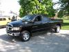
My truck is a 2003 ford f150 4x4 5.4l v8... looking to get the most fuel efficiency I can get while still having function. (I tried to post a pic of the template over my truck, however I apparently do not have enough posts to add a picture  ) |
|
|
|
|
11-04-2014, 12:30 AM
|
#45 (permalink)
|
|
Diesel Trucker
Join Date: Apr 2012
Location: Aspers, PA
Posts: 35
JD - '04 Dodge Ram 2500 QCLB 4x4 SLT Last 3: 18.93 mpg (US)
Thanks: 17
Thanked 22 Times in 13 Posts
|
Quote:
Originally Posted by bmack2
I think this is how I am going to do it.
-3"X3" for sides along most of the bed length
-2"x4" or closest steel stock I can find for the main support
-then either 3/4" or 1" angle for the frame of the wedge (should be roughly half the weight of the square tube yet more than strong enough for my needs I feel)
-then drill and tap bolt holes to attach the aluminum, i figure it may take longer but easier to change a sheet if I need to.
Thanks for the heads up Charlie, I saw that point earlier and through previous research decided on not going right down to the tailgate, but I was under the impression 11* would be the best? should I stick with 8*? I took measurements tonight and the length of the base of the wedge would be 75" and height would be 21" at the cab. Im fairly set on not rounding the corners as this would make everything exponentially more time consuming.
My truck is a 2003 ford f150 4x4 5.4l v8... looking to get the most fuel efficiency I can get while still having function. (I tried to post a pic of the template over my truck, however I apparently do not have enough posts to add a picture ) |
It should be more than strong enough. I know I should/could be lighter BUT I can also haul a butt load of weight on the "headache" rack without the wedge in place. After I got the entire wedge frame built and before I got the aluminum skin on we had to pick up an "outsize" load for work. The crate was 9' long x 6.5' wide x 1.5' deep, weighed 800lbs. we just loaded it on top of the wedge frame and tied 'er down. No sweat.
__________________
Bob,
Dodge Ram '04.5, 2500 HO, Auto, QCLB, 4x4, CAI, 4" turbo back, Smarty Jr, Airdog 100. So Far
Previous; Dodge Ram '03, 3500, QCLB, 4x4, Dually, RIP
|
|
|
|
|
11-04-2014, 03:07 PM
|
#46 (permalink)
|
|
Aero Deshi
Join Date: Jan 2010
Location: Vero Beach, FL
Posts: 1,065
Thanks: 430
Thanked 669 Times in 358 Posts
|
Without knowing the exact body/bed combo you have, here's what I came up with. And yes, the 8° angle will do the trick. Reference page 84 & 85 of this. Truck Aero Paper. I'm not making this up. An Arab from Cal State did his homework.
The conclusion I draw is that at 8°, you get darn near the best Cd, your Lift Coefficient is still very low, AND...You get a ton more space to use under the cap. Best of all worlds.
I figure 8° will get you an 11.5" rear height above the tailgate based on a 75" run and 21" front height. 11° is 8" above the gate.

Also, without knowing quite how to put this lightly, by using flat surfaces and not radiusing the edges, you have 2 strikes against you design wise. The air wants to change directions gradually. By keeping your primary surfaces flat, you introduce a sudden break at the roof to cap transition, the steeper your cap, the more sudden the break, the less the air will like it. With sharp edges, when you create a steeper cap, you lower the pressure on the roof of the cap, the higher pressures on the sides will want to fill this low in, and with no radius to ease the transition, it will tend to create an energy robbing vortex. Again, the steeper the angle, the bigger the vortex. Steeper Bad, Shallow Good. Really look at the chart on the reference paper Pg 85, you see a great improvement at just 5°, so 8° will be a good improvement without risking turning your truck into a massive drag creating vortex generator.
2 other side effects of the cap you'll discover are your truck will be quieter at highway speeds, and (being from Ontario you'll love this) in the winter, your truck will feel like an arrow going down the road at highway speed in icy conditions. I don't know what it is, but my truck felt like it was much more stable with the aerocap on than without in the slippery weather. I think it's the Lift Coefficient going way down that does it. My GMC would always feel like it wanted to spin out at fast speeds with out the cap, and with it, it never slid once.
Hope this helps ya!
Charlie |
|
|
|
|
The Following 2 Users Say Thank You to ChazInMT For This Useful Post:
|
|
|
11-04-2014, 05:47 PM
|
#47 (permalink)
|
|
EcoModding Lurker
Join Date: Sep 2013
Location: Ontario
Posts: 6
Thanks: 5
Thanked 0 Times in 0 Posts
|
Thanks charlie,
I looked at the pages you said, wouldnt the best cap be the one with the lowest drag coefficient? Based on table 4.6.1 wouldnt this be around 10-12*? or because this is done at relatively low velocities 3m/s does this make a difference? I know that laminar flow depends on velocity so this would probably be what youre talking about forming vortex where this test in the paper would not?
|
|
|
|
|
11-05-2014, 10:52 AM
|
#48 (permalink)
|
|
Aero Deshi
Join Date: Jan 2010
Location: Vero Beach, FL
Posts: 1,065
Thanks: 430
Thanked 669 Times in 358 Posts
|
Quote:
Originally Posted by bmack2
Thanks charlie,
I looked at the pages you said, wouldnt the best cap be the one with the lowest drag coefficient?
|
Yes, and NO. At 8° you'll be within 1% of the improvement potential, technically more like 4% of the total gain, but still, you've made a tremendous improvement. If you drop it further, the lift coefficient starts going back up. Also, and most really important here, your design is very basic, you have no curves, therefore, if you try and push it, you will likely end up with more drag.
Quote:
Originally Posted by bmack2
I know that laminar flow depends on velocity so this would probably be what youre talking about forming vortex where this test in the paper would not?
|
The vortex will generate at 5 mph, speed is not important to whether and aero feature will function, at least not until you reach several hundred mph. To directly address your question, Laminar flow will never occur on your truck. It is, and always will be, turbulent. The vortex formation I refer to is not illustrated in the paper, it is more like long horizontal tornadoes being dragged behind like 300 ft party streamers off the tops of your tail lights.
Again, 8° gives you a tremendous gain in aero efficiency, within a few % of ideal, and the most utility with regard to under cap capacity. It also stays away from the potential to go too far and start giving the gains back. I know you want to do the most you can, and it does intuitively seem as though 11° to 13° will "Shrink the wake" more and thus be more efficient, but this is NOT true. Efficiency has to do with disrupting the air as little as possible as we drive through it, the less we move it, the less energy it takes.
I look at the relatively puny amount of air a fan moves, and consider the amount of electric energy required to move it. It really does take some power to move air. Consider that when you drive your truck down a quiet country road on a calm day. The air above the road before you arrive is just sitting there, then Voooom....you ram through it. If you're in a VW XL1, that air will likely just waft about a bit and return to being calm in short order. When you drive a pick up through it, you really stir up the air and cause it to move quite far from where it started out, this displacement, or movement of air is where your energy is going. A vortex requires a lot of energy to establish itself and therefore creates a lot of drag. 60% of what we do when we design aero shapes is to avoid the vortex.
Please trust me, I have thought about these things long and hard for the better part of 4 years, if you want to optimize your cap, you'll have an 11" height in the back. 5° would give you a 15" rear height, 11° will have 8". If this were my project, I'd build it with a 13" height, and curve the top and sides, and know I've done the best I could, zero doubt. The minimization of the lift coefficient to me has a huge draw, since you can't optimize both, aim for the middle. |
|
|
|
|
The Following 2 Users Say Thank You to ChazInMT For This Useful Post:
|
|
|
11-05-2014, 03:51 PM
|
#49 (permalink)
|
|
EcoModding Lurker
Join Date: Sep 2013
Location: Ontario
Posts: 6
Thanks: 5
Thanked 0 Times in 0 Posts
|
Thanks so much with the design help! My buddy is installing the outlet for my welder this weekend, so should be well on my way in the next few weeks. I checked out the 3/4 inch angle iron last night and decided it is more than strong enough.
Bob, I am just curious about how you latch the wedge shut, I tried to look closely at the pictures, from what I can tell its just a hole in the 3X3 and in the wedge in which you put a pin through it? And is there a specific type of hinge you feel I should use for the top or would a regular door hinge work from home depot. I checked grainger but cant seem to find what fits your description.
We shall see how this model works and maybe in the future I will weld one up in aluminum and add in smooth edges, however can not afford that at the moment money and time wise. Surplus steel is pretty much the most I can afford.
|
|
|
|
|
07-31-2015, 10:27 PM
|
#50 (permalink)
|
|
Banned
Join Date: Oct 2009
Location: Fort Worth, Texas
Posts: 2,442
Thanks: 1,422
Thanked 737 Times in 557 Posts
|
Bumped for another discussion underway on CF.
|
|
|
|
|