01-24-2012, 11:25 AM
|
#21 (permalink)
|
|
Master EcoModder
Join Date: Dec 2011
Location: Boise Idaho
Posts: 842
Thanks: 39
Thanked 89 Times in 69 Posts
|
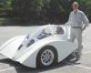
Well, for better or worse, the first body is roughed out, so not much change gonna happen. The fact it is 3 dimensional means I did some pretty crazy stuff - might have lose some attached flow here and there, but truth is cool looking sells a LOT better then a pinched off turd which is what perfect looks like.
Also true is the hood is wide and low, and the cockpit is high and narrow. Will air stack up in front of the windshield, and fall off to each side to fill the holes made by the hood and front tires? Pretty tough to model, and for sure speed of vehicle matters a LOT.
meanwhile I am filling fiberglass and making it all pretty to pull a permanent mold.
|
|
|

|
 Today Today
|
|
|
|
 Other popular topics in this forum...
|
|
|
|
|
01-24-2012, 11:51 AM
|
#22 (permalink)
|
|
A Legend in his Own Mind
Join Date: Dec 2011
Location: Atlanta
Posts: 281
Thanks: 52
Thanked 91 Times in 54 Posts
|
Quote:
Originally Posted by drmiller100

Also true is the hood is wide and low, and the cockpit is high and narrow. Will air stack up in front of the windshield, and fall off to each side to fill the holes made by the hood and front tires? Pretty tough to model, and for sure speed of vehicle matters a LOT.
meanwhile I am filling fiberglass and making it all pretty to pull a permanent mold.
|
If you do some tufting, you may find the flow gives you suggestions for improving the flow around the wheels and fenders. Tufts can be placed in the space behind the wheels, (away from the body surface, on things like a tensioned thread from outer fender edge to door, or rigid little posts) to get a better feel for whats going on. The fender molds would be pretty easy to change, if required.
You're making great progress. |
|
|
|
|
01-24-2012, 06:01 PM
|
#23 (permalink)
|
|
Master EcoModder
Join Date: Jan 2008
Location: Sanger,Texas,U.S.A.
Posts: 16,534
Thanks: 24,520
Thanked 7,436 Times in 4,817 Posts
|
'Template' thread
Quote:
Originally Posted by Grant-53
The Template C appears to be an exponential curve as in a Poisson distribution and will generate lift if air flows under it. Cars vary in length, ground clearance, and height. Consider the ground clearance (6 to 9 inches) as considerable work has been done in the last decades on ground effects and downforce at high speeds. A combination of ellipsiod quadrants can approximate a 5:1 streamline shape. Functions can be calculated using a spreadsheet program and plotted as 3D graphs. Experiment with positioning an angled 'bug deflector' on the hood reduce high pressure at the base of the windshield.
|
For a complete discussion of the evolution of the 'Template,' please see the thread:"Aerodynamic Streamlining Template," Parts:A,B,C,D----------- |
|
|
|
|
The Following User Says Thank You to aerohead For This Useful Post:
|
|
|
01-24-2012, 08:12 PM
|
#24 (permalink)
|
|
Master EcoModder
Join Date: Dec 2011
Location: Boise Idaho
Posts: 842
Thanks: 39
Thanked 89 Times in 69 Posts
|
Quote:
Originally Posted by Ken Fry
If you do some tufting, you may find the flow gives you suggestions for improving the flow around the wheels and fenders. Tufts can be placed in the space behind the wheels, (away from the body surface, on things like a tensioned thread from outer fender edge to door, or rigid little posts) to get a better feel for whats going on. The fender molds would be pretty easy to change, if required.
You're making great progress.
|
thanks!
Like you are hinting, I am to the point I need to get a car on the road. I have LOTS of unresolved things, which will get lined out as I get closer.
I did figure out how to make the mold so I can have either the big air scoops on the side, or smooth sides for better air flow.
I have three areas on the car which can be improved. Time to make it run though! |
|
|
|
|
01-25-2012, 11:35 AM
|
#25 (permalink)
|
|
Master EcoModder
Join Date: Feb 2010
Location: Elmira, NY
Posts: 1,794
Thanks: 320
Thanked 361 Times in 300 Posts
|
If we are modifying an existing car or truck (like my '95 Geo Prism/Corolla) to come closer to the Template profile then we need to smooth the flow over the windshield. Comparing the hood and cowl of our 2002 Dodge Grand Caravan there is a smoother transition and the cowl is deflecting air above the wiper assembly. The windshield angle, the angle of the deflector, and the distance from the base of the windshield to the deflector are variables to be investigated.
I first saw this used on Subaru rally cars in the early '70s. I have had two stone chips in the base of my windshield in the last year so I expect this to help on that account. This is mainly for vehicles with flat hoods and near verticle windshields such as pickup trucks and older sedans. Just make sure you don't accidently block washer solvent jets.
|
|
|
|
|
01-25-2012, 06:50 PM
|
#26 (permalink)
|
|
Master EcoModder
Join Date: Jan 2008
Location: Sanger,Texas,U.S.A.
Posts: 16,534
Thanks: 24,520
Thanked 7,436 Times in 4,817 Posts
|
cowl area
Quote:
Originally Posted by Grant-53
If we are modifying an existing car or truck (like my '95 Geo Prism/Corolla) to come closer to the Template profile then we need to smooth the flow over the windshield. Comparing the hood and cowl of our 2002 Dodge Grand Caravan there is a smoother transition and the cowl is deflecting air above the wiper assembly. The windshield angle, the angle of the deflector, and the distance from the base of the windshield to the deflector are variables to be investigated.
I first saw this used on Subaru rally cars in the early '70s. I have had two stone chips in the base of my windshield in the last year so I expect this to help on that account. This is mainly for vehicles with flat hoods and near verticle windshields such as pickup trucks and older sedans. Just make sure you don't accidently block washer solvent jets.
|
Walter Lay did a comprehensive series of wind tunnel studies with built-up models.The results showed no benefit between a front end like GM's Sunracer,or your Prism/Corolla. |
|
|
|
|
The Following User Says Thank You to aerohead For This Useful Post:
|
|
|
01-27-2012, 02:07 PM
|
#27 (permalink)
|
|
Master EcoModder
Join Date: Feb 2010
Location: Elmira, NY
Posts: 1,794
Thanks: 320
Thanked 361 Times in 300 Posts
|
Do you mean the late Prof. Walter E. Lay from Univ. of Michigan? Could you give the title and date of the study? Thanks.
|
|
|
|
|
01-27-2012, 06:19 PM
|
#28 (permalink)
|
|
Master EcoModder
Join Date: Jan 2008
Location: Sanger,Texas,U.S.A.
Posts: 16,534
Thanks: 24,520
Thanked 7,436 Times in 4,817 Posts
|
Lay
Quote:
Originally Posted by Grant-53
Do you mean the late Prof. Walter E. Lay from Univ. of Michigan? Could you give the title and date of the study? Thanks.
|
Yes,same man.Lay published in 1933.Kamm picked up on his work in 1935.Hucho shows an abbreviated tabulation of Lay's results.The whole thing is in Aerodynamiks des Kraftfahrtzeugs, by Fachsenfeld,1951.
Lay demonstrated that it required a very nasty cowl/windshield ( the HUMMER H-1 would qualify) to trash the airflow over the windshield header.
There will be a small burble of air at the base of the windshield for fresh air ventilation.The outer flow field skips mover this entire area with what Ludwig Prandtl termed, a 'line of discontinuity',avoiding sharp turns over the top and around the A-pillars.You can see this in most wind tunnel smoke flow photos.
|
|
|
|
|
The Following User Says Thank You to aerohead For This Useful Post:
|
|
|