05-02-2011, 02:56 PM
|
#21 (permalink)
|
|
EcoModding Apprentice
Join Date: Dec 2009
Location: Wisconsin
Posts: 233
Thanks: 71
Thanked 2 Times in 2 Posts
|
What has more drag, a solid wheel cover or one with holes in it?
I have no idea what the real answers to these questions are, I'm just saying I don't think you can make those kinds of assumptions. I will see if I can come up with any research on it.
|
|
|

|
 Today Today
|
|
|
|
 Other popular topics in this forum...
|
|
|
|
|
05-02-2011, 03:51 PM
|
#22 (permalink)
|
|
EcoModding Lurcher
Join Date: Dec 2010
Location: Los Angeles
Posts: 333
Thanks: 151
Thanked 109 Times in 80 Posts
|
Hi justjohn,
I have a recollection of a table of shapes and their drag coefficients. I'm thinking it was Eshbach or someting in the Wiley series. Anyway, I think the table had all the usual suspects; flat plate, hemisphere, cone... but also a couple of mesh sizes too. I'm sure the drag on hardware cloth was about 4 or 5 times a flat plate. Have you seen a table like that?
-mort
Quote:
Originally Posted by justjohn

What has more drag, a solid wheel cover or one with holes in it?
I have no idea what the real answers to these questions are, I'm just saying I don't think you can make those kinds of assumptions. I will see if I can come up with any research on it.
|
|
|
|
|
|
05-02-2011, 04:13 PM
|
#23 (permalink)
|
|
EcoModding Apprentice
Join Date: Dec 2009
Location: Wisconsin
Posts: 233
Thanks: 71
Thanked 2 Times in 2 Posts
|
No I have not. If you come across it again please link us!
Edit:
Seems hard to find info on this that's free, but I did find a little.
This says that perforating a solid body increases its drag
http://www.cpom.org/people/jcrh/JIA(3).pdf
This has boundary layer info that may or may not be useful. Didn't have time to sort through.
http://www-htgl.stanford.edu/bradsha...reen_paper.pdf
Last edited by justjohn; 05-02-2011 at 04:53 PM..
|
|
|
|
|
05-02-2011, 07:11 PM
|
#24 (permalink)
|
|
n00b.... sortof..
Join Date: Oct 2010
Location: SFL
Posts: 345
Thanks: 37
Thanked 19 Times in 18 Posts
|
Quote:
Originally Posted by instarx
Δ
"Rated for"?
|
read above, already answered
Quote:
Originally Posted by instarx
You sound very confident. However, this is opposed to everything I was taught in grad school about pressure, flow, velocity and how they relate to resistance to airflow. The velocity of the air makes a huge difference in flow resistance. In fact, the resistance to flow across any restriction increases as the square of the velocity.
The formula is V=4005*√VP, where VP is the velocity pressure in inches of water (measured as the change in pressure, ΔP, across the screen). The formula indicates that as the air velocity increases linearly the resistance to flow by the screen increases exponentially. (4005 is just a constant and can be ignored here).
So I think I will stick to the engineering formulas that say as the vehicle's speed increases, the screen (vertical, slanted, whatever) will block a greater and greater proportion of the incoming air. How much screen, how many layers, or how small a mesh size are just engineering details to be worked out. But the idea of using mesh as a variable air block material is a good one.
|
I am very confident, before anything, lets put grad school vs more than 12 yrs hands on experience in the screening/aluminum industry, within a hurricane zone (S.FL.)
if your formula was to work, then every time we get even a heavy thunderstorm with 50+ mph winds (just about an every day occurrence in the summer), it would pull that screen right off the rails... every single time. (which would be good for me, since then Id have more work than I could keep up with) 
if you doubt me, take a moment and actually look at the screens in your home, either wall or window.
you can push that screen out from the front with little effort. certainly much less force than 40-50 mph winds generate.
now, take that same screening material and put it at a 45 /.
now you have almost doubled its resistance. so yes, it would make an effective blocking method IF you have a decent angle to work with. but as a straight on application, then your only going to see the basic rating of 34%.
remember, we are talking about almost the thickest screening material you can find, which is .13.
your average screen is .11
__________________
~Mike

|
|
|
|
|
05-02-2011, 10:17 PM
|
#25 (permalink)
|
|
EcoModding Lurker
Join Date: Jul 2008
Location: Chicago, IL
Posts: 55
Thanks: 0
Thanked 7 Times in 6 Posts
|
The article with the porous cylinders is completely irrelevant to this discussion. In that article the holes are affecting parallel flow which is akin to using screen as a belly pan. We however are talking about perpendicular flow. I found this great article talking about mesh and air flow as it relates to fume hoods.
http://ateam.lbl.gov/hightech/fumeho..._Fume_Hood.pdf
In the article they determine an equation calculating the static pressure created at the face of the screen that is dependent on the air velocity.
P = (V^1.5)/(42.8*10^2.59A)
P = pressure in pascals, V = velocity in feet per minute and A = the free hole area. 1 MPH = 88 FPM.
Using this equation you can calculate the static pressure generated at the face of the screen.

If we take the smallest free hole area at 60 MPH we get over 2000 pascals of static pressure. The question is can this much static pressure block air flow through a screen.
I also found this article about the effect of static pressure on the cfm of a fan http://www.asi.ksu.edu/DesktopModule...ocumentID=5131
At the end of the article there is a table showing how CFM of a fan decreases with increasing static pressure. In that table the highest static pressure is 0.30 in. water. There are 248.9 pascals in 1 in. water. So 2018 Pascals converts to 8.1 in. water. If you graph the fan CFM vs Static Pressure and extrapolate forward all of the fans listed go to 0 CFM by 0.6 in. water.

And a 25% free hole area screen at 60 MPH generates 8.1 in. water in static pressure. You cannot tell me there will not be some blocking going on with a low enough free hole area screen. I am confident the correct mesh will block most air flow at highway speeds. Some air will likely still be forced through. Is the trade off of not having 100% blocking like a solid piece for a grill block at high speed worth it to gain low speed air flow? If you can have both high speed blocking and low speed flow can you block more of your grill without risking overheating? I think the articles I found and the calculations I have done form a solid theory. Now all that remains is the testing.
Quote:
|
if your formula was to work, then every time we get even a heavy thunderstorm with 50+ mph winds (just about an every day occurrence in the summer), it would pull that screen right off the rails... every single time. (which would be good for me, since then Id have more work than I could keep up with)
|
Correct me if I am wrong, from what I could find most residential screens have a free hole area of ~70%. Looking in the table of calculations we see the typical window screen generates 6.83% of the static pressure of a 25% free hole area screen. So the typical household screen is not in the same ball park as one we would consider using for a grill block.
__________________

|
|
|
|
|
The Following 2 Users Say Thank You to jthistle For This Useful Post:
|
|
|
05-02-2011, 10:31 PM
|
#26 (permalink)
|
|
Master EcoModder
Join Date: Oct 2009
Location: Texas
Posts: 3,523
Thanks: 2,203
Thanked 664 Times in 478 Posts
|
here is my stealth block.......
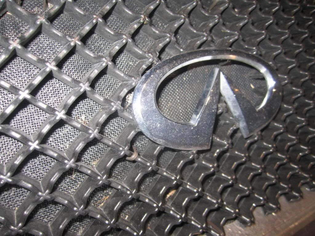
That is the thickest available at the hardware.
I have a wire screen behind it that is zipped tied to hole the thick screen in place |
|
|
|
|
05-02-2011, 11:25 PM
|
#27 (permalink)
|
|
EcoModding Apprentice
Join Date: Dec 2009
Location: Wisconsin
Posts: 233
Thanks: 71
Thanked 2 Times in 2 Posts
|
I personally want to know results for both perpendicular and parallel flow. Any surface you create is never going to be perfectly perpendicular or perfectly parallel to the airflow so its important to me what happens on both ends and in between. Anyway...
Good find on the hood article, I think we're getting somewhere now. The fan article I don't find particularly useful; I think to complement the hood article we need something that shows how much air goes through at what speeds/pressures, and most importantly, how much drag is created.
Remember, I said from the beginning I don't doubt that more flow will be blocked at higher airspeed. The question is, what if you're adding some ridiculous amount of drag that completely negates the benefits?
|
|
|
|
|
05-02-2011, 11:48 PM
|
#28 (permalink)
|
|
EcoModding Apprentice
Join Date: Dec 2009
Location: Wisconsin
Posts: 233
Thanks: 71
Thanked 2 Times in 2 Posts
|
Okay found a good one, but unfortunately even the highest velocity and thickest screens they tested are at the lower bound of what's interesting to us. Still, it's a good starting point.
Information Bridge: DOE Scientific and Technical Information - Sponsored by OSTI
P.S.
They said at higher reynolds numbers vortex shedding would occur, but I don't know enough about aerodynamics to know if that would even happen when using as a grill block, or what affect it would have on drag/airflow. |
|
|
|
|
05-03-2011, 12:38 AM
|
#29 (permalink)
|
|
n00b.... sortof..
Join Date: Oct 2010
Location: SFL
Posts: 345
Thanks: 37
Thanked 19 Times in 18 Posts
|
Quote:
Originally Posted by jthistle
Correct me if I am wrong, from what I could find most residential screens have a free hole area of ~70%. Looking in the table of calculations we see the typical window screen generates 6.83% of the static pressure of a 25% free hole area screen. So the typical household screen is not in the same ball park as one we would consider using for a grill block.
|
your not wrong, but how much open area do you believe the .13 has ?
.13 is designated for mites and other insects smaller than a flea, and has en effective coverage area of about 34%
no matter how you cut it, how many graphs you post, how many equations and how you arrange them, it isnt going to change a thing.
you keep forgetting I bring "real" world experience to the table, I do this for a living and have done so for more than 12 yrs.
as I stated, and will continue to state, minus a 45* / your not going to see much benefit over stock.
prove me wrong, get some screen, put on the front of your vehicle and post some real world data.
but, to prove it, you going to have to rig something up to put that screen at a straight on surface, that or you should go ahead and concede defeat.
(BTW, that is a trick challenge, and I'll even tell you why. Ive already done it, it made 0 improvement on my 99 Ranger XLT)
__________________
~Mike
|
|
|
|
|
05-03-2011, 04:04 AM
|
#30 (permalink)
|
|
EcoModding Lurcher
Join Date: Dec 2010
Location: Los Angeles
Posts: 333
Thanks: 151
Thanked 109 Times in 80 Posts
|
Hi justjohn,
This is good. Looking at 80 and 100 mesh. Window screen is usually 14 or 16 mesh, so this is a lot tighter than what I think most are interested in here.
Information Bridge: DOE Scientific and Technical Information - Sponsored by OSTI
Attached is the key graph1. Note drag goes from 6 to about 1 as the air speed increases! That's the opposite from what I expected.
I found a paper at the University of Southern Queensland about fire supression using double layers of wire mesh. These tests were on larger mesh, the wire about twice as big as window screen and about 10x10 mesh was the smallest with 34% porosity. Attached is the cherry-picked graph2 showing drag coefficient of around 4 but generally constant for air speed. The other tests show that wire size and porosity are very important for drag. Finer wire and less open space increasing drag. Large wire and large mesh, even just 4x4 has a drag well below 0.5
Window screen might have a Cd of about 5 for highway speeds. Or 5 times worse than a flat plate.
-mort
|
|
|
|
|
The Following User Says Thank You to mort For This Useful Post:
|
|
|