07-14-2015, 10:41 AM
|
This thread is in the EcoModder Project Library |
#1 (permalink)
|
|
Master EcoModder
Join Date: Apr 2012
Location: Evensville, TN
Posts: 676
Thanks: 237
Thanked 580 Times in 322 Posts
|
DIY Electric Fan Conversion and Controller
Overview:
Below is a complete writeup for a reliable robust electric fan and controller setup for a second generation Tacoma that I built. Most of this is universal and could be implemented on any vehicle. I am not going to go into great detail on things covered in the vehicle manual or common how-to skills mainly to keep this from being a thirty page write-up, Google is your friend. I tried very hard to pass along the pertinent information without getting down in the weeds or boring you with unimportant text.
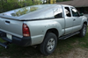
Anyway, the recipient:
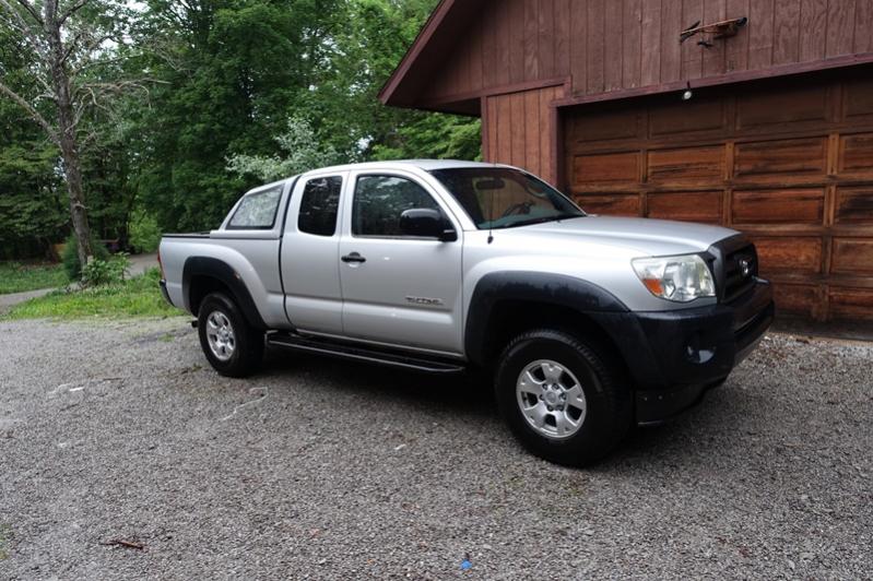
The main benefits I wanted to get was increased fuel economy, better cooling offroad at low speeds, and the ability to disable the fans for water crossings. My requirements for the system were: reliability on par with OEM installations, function like factory electric fans, utilize high efficiency fans, provide appropriate airflow for cooling, and not draw excess electrical power. The control should be automatic but able to be overridden off or on with the current status indicated in the cab with a clear warning if the system is overridden off. The system should be robust for use on and off road and the portion exterior the cab should be water resistant.
Disclaimer: If you decide to pursue this, do so at your own risk. I am not responsible for you and your actions. This is not a simple project and if not done correctly you risk hurting yourself, hurting others, and/or destroying your vehicle. I am posting this for free out of the goodwill of my heart, and will do my best to answer questions posted in this thread. However since this isnt my job and I am not going to make a penny off of this I cannot answer detailed technical/installation questions or hold someones hand through a conversion. I have no desire to make or sell any of these items.
|
|
|

|
|
The Following 4 Users Say Thank You to aardvarcus For This Useful Post:
|
|
 Today Today
|
|
|
|
 Other popular topics in this forum...
|
|
|
|
|
07-14-2015, 10:42 AM
|
#2 (permalink)
|
|
Master EcoModder
Join Date: Apr 2012
Location: Evensville, TN
Posts: 676
Thanks: 237
Thanked 580 Times in 322 Posts
|
Fan Selection and Mounting:
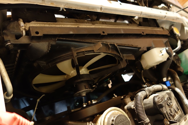
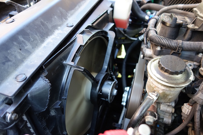
When it came to fans, I did not know the reliability of aftermarket fans so I focused in on repurposing OEM fans. Many fans used in swaps I researched drew more power than I wanted or were older flat blade designs. I finally settled on the dual electric fans from a V6 Toyota Camry, 2007-2011 style. The good points about this fan are that it will provide sufficient cooling, won't strain the electrical system, is a modern design, and had a closely fitting shroud. The bad points about this fan was stock it uses a voltage controller so no low/high wires, it is too wide to fit right in my truck without modification, and I found no prior swaps with this fan. Being stubborn, I decided I could work around the negatives and ordered the Camry fan anyway. The imperfect fitment:
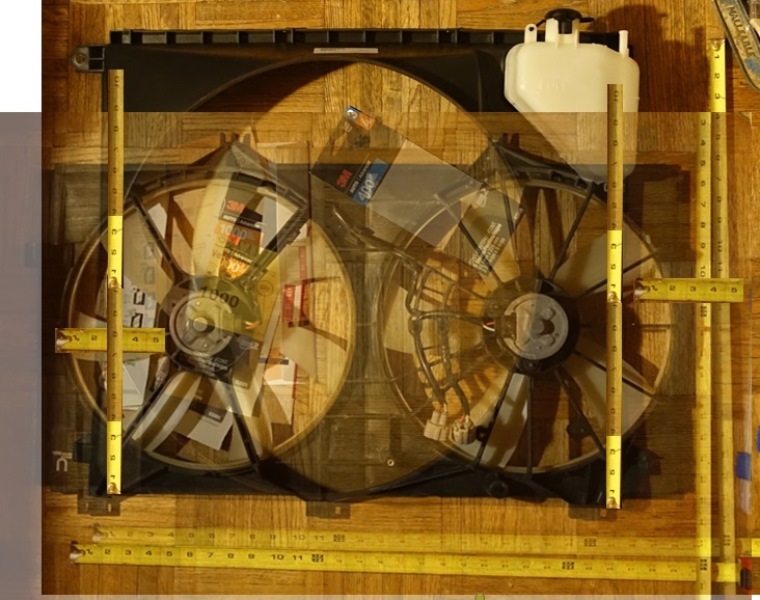
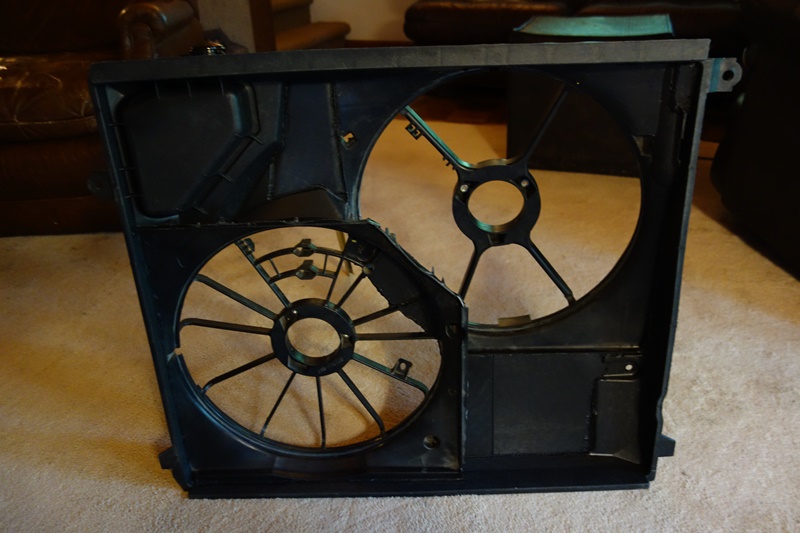
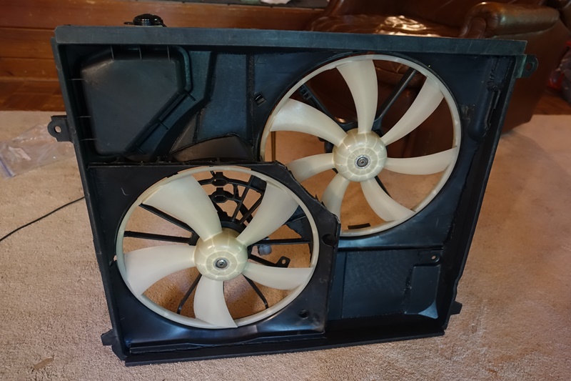
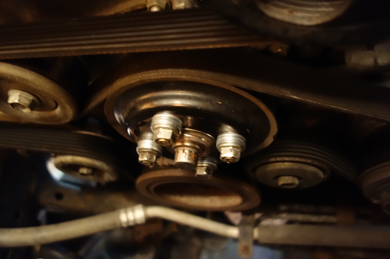
To maximize efficiency and cooling the new shroud needs to cover the entire radiator, plus my radiator overflow tank is molded into the Tacoma shroud so I cant just remove it. I ordered an extra fan shroud for the Tacoma and decided to fit the new fans and their shroud into the old shroud. I ordered new parts to modify so that I could return the truck to factory and driving the truck. I removed the electric fans and motors and integrated the Camry and Tacoma shrouds together so the electric fan parts would mount correctly and the Tacoma fan shroud base would still bolt right up. I separated the two sides of the Camry shroud and mounting them so that one was in the upper left hand corner of the Tacoma shroud and the other was in the lower right hand corner. My radiator overflow tank is in the upper right hand corner. The fans overlap in the center to keep from hanging off the edges. I used an old 40W soldering iron to heat weld and integrate the shrouds together. Lastly I used parts and pieces that I had to remove from the shrouds to fill any blank places in the shroud so that the entire radiator would be covered and ducted to the fans. I also covered over the overlap portion of the fans so they would not both pull the same air. I drained the stock radiator overflow tank, removed the engine driven fan and stock shroud, reinstalled the water pump pulley with washers for spacers, installed the new shroud with electric fans and tank, and refilled the radiator overflow tank. (Note this is not written in order of installation, you should have all your control and power circuits built, tested, and mostly installed prior to this step.)

 |
|
|
|
|
The Following 4 Users Say Thank You to aardvarcus For This Useful Post:
|
|
|
07-14-2015, 10:42 AM
|
#3 (permalink)
|
|
Master EcoModder
Join Date: Apr 2012
Location: Evensville, TN
Posts: 676
Thanks: 237
Thanked 580 Times in 322 Posts
|
Fan Control Basics:
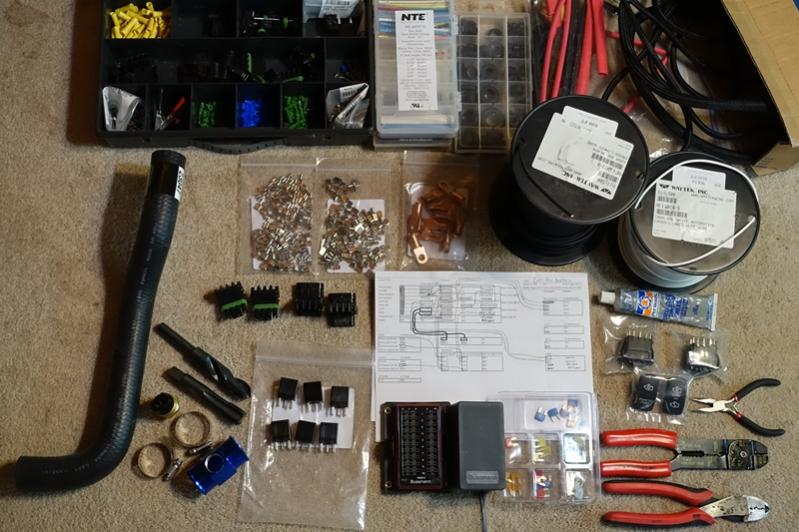
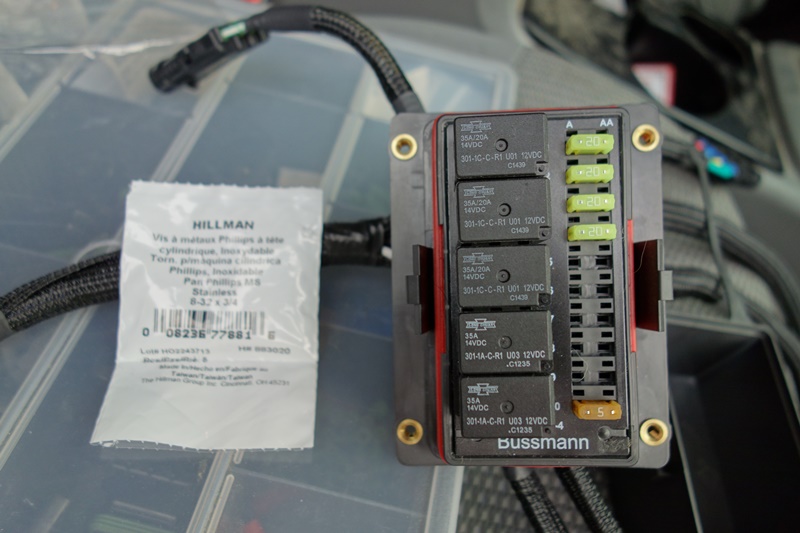
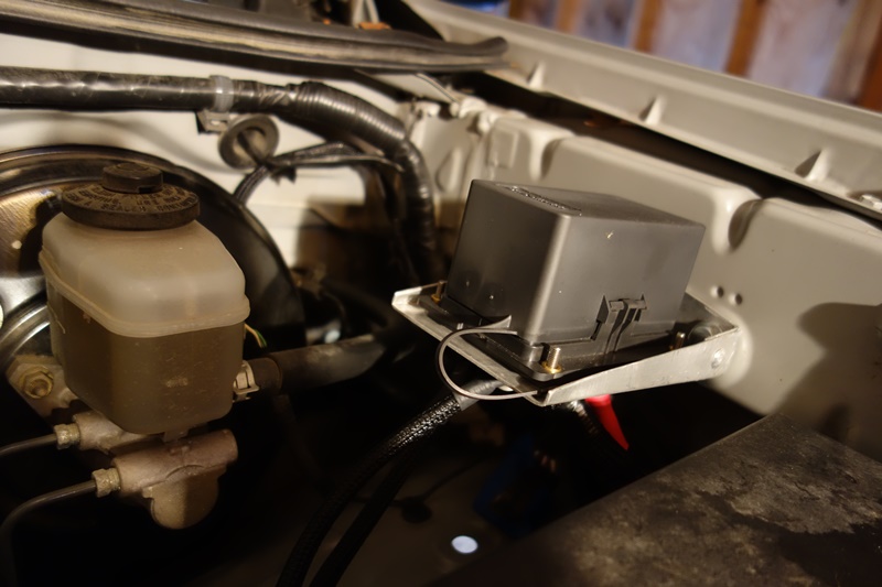
Looking at controllers, I found typically the reliability to be sub-par and many used a temperature sensor stuck in the radiator fins which I am not a big fan of. I decided to assemble a basic two speed controller myself. For the base of the fan controller, I decided to use a Cooper Bussmann RTMR 15303-4-0-4 panel. I have used these for prior automotive wiring projects and already had a selection of pins and plugs to go in them. I chose a non-bussed model because a buss would interfere with some of the logic. Also the non-bussed panels are easier to waterproof. I made an aluminum RTMR under hood mount for my Tacoma, these are for sale online but simple enough to make. I used 5 pin Song Chuan ISO 280 micro relays, because the logic requires access to both the on and off positions of the relay. I also used a selection of wire, fuses, weatherpack connectors, heat shrink, protective wire loom, spade terminals, and a variety of other small electrical components.
As previously stated, the Camry fan does not have low/high functionality because in the Camry it actually has a voltage controller to control the speed. I got a free Camry controller when I bought the Camry fans (used out of a junkyard) and after opening it, quickly discovered it was of absolutely no use without a micro-controller, which is beyond the scope of this swap. I wanted to have two speed settings, but I wasn't too keen on using resistors to slow down the fan, since that method wastes energy heating the resistor. I decided the best way to slow the fans but maintain full efficiency would be to have the two fans wired in series for the low speed, and then take them out of being in series and put them in parallel for the high speed. I will explain how that is accomplished in the logic section below. Having the fans in series would divide the voltage each fan saw in half, while being in parallel would allow full voltage at both fans. Testing the fans with a current meter and a battery, the fans in series pulled roughly 3 amps for the pair and in parallel they pulled about 5 amps each so about 10 amps total.
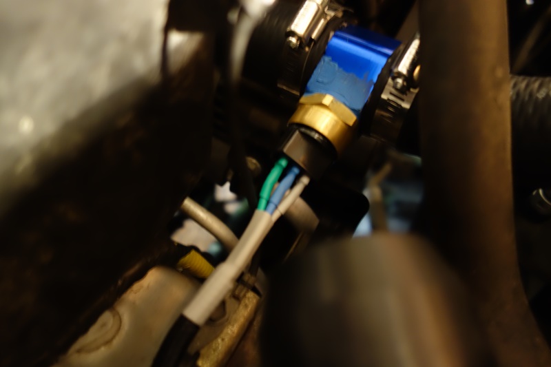
The controller needs to know what the engine temperature is. I used a Beck/Arnley 2011266 (201-1266) Radiator Fan Switch, which threads into a M22 1.5 thread. This is a two temperature switch, kicks on low about 195 F and high about 205 F, and kicks off a few degrees less than the kick on temperatures. This is a ground triggering switch, so it is connected to the ground side of the control relays. The key part of this temperature switch is insulated ¼” female spade terminals fit the prongs exactly, so no searching for rare factory connectors. I was unable to locate a M22 1.5 hose adapter (very rare), so I purchased an inexpensive 36mm 1.42" 1/8 NPT Water Temp Gauge Radiator Hose Sensor Adaptor, a 13/16 Drill Bit, and a M22 1.5 Tap. I drilled out and tapped the hose adapter, installed the temperature switch, cut a section out of a spare Tacoma upper radiator hose, installed the hose adapter, partially drained the coolant from the radiator, installed the new hose, and replaced the coolant following the procedure in the manual. I had this made early on, but put this in the truck at the same time I installed the new fan shroud, one of the last steps in the swap.
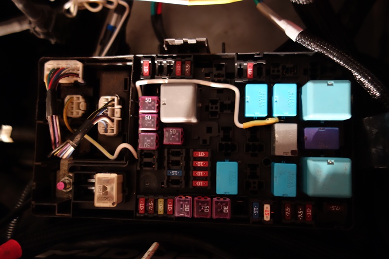
The fan controller also needs to know when the AC compressor is on, and should be running at least on low when the compressor is compressing. I did this by tying into the output of the relay that runs the magnetic clutch using a modified fuse tap. Note this is a high power positive circuit being tapped and cannot directly be used to control the fan relays which are ground triggered, so I ran this through a fuse and then used this as a positive trigger (pin 85) of a fourth relay. When the compressor kicks on, the fourth relay now turns on, which connects the fan low relay trigger to ground pins 30 using and 87 of the relay. This will make the fan low circuit kick on, exactly like if the temperature switch kicked on low.
 |
|
|
|
|
The Following 3 Users Say Thank You to aardvarcus For This Useful Post:
|
|
|
07-14-2015, 10:43 AM
|
#4 (permalink)
|
|
Master EcoModder
Join Date: Apr 2012
Location: Evensville, TN
Posts: 676
Thanks: 237
Thanked 580 Times in 322 Posts
|
Power, Switches, and Indicators:
The multiple main power feeds for the fans come directly from a crimped lug on the battery positive terminal and run through fuses on the RTMR panel before going to their destinations. All the ground wires under the hood similarly run from their destinations and come together to run to the battery negative terminal through a crimped lug.
Within the cab, the accessory circuit was tapped using a fuse tap (on the protected side of the fuse), and is used for the fan relay positive triggers (pins 85) of the main three relays and for the indicators in the cab. Basically, if the truck is not on none of the fans or other things will run so you can’t accidentally kill your battery unless you leave the truck on. All the grounds in the cab come together to run to a grounded bolt just below the fuse panel.
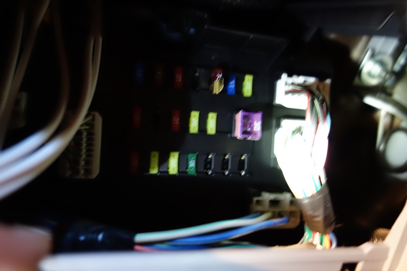
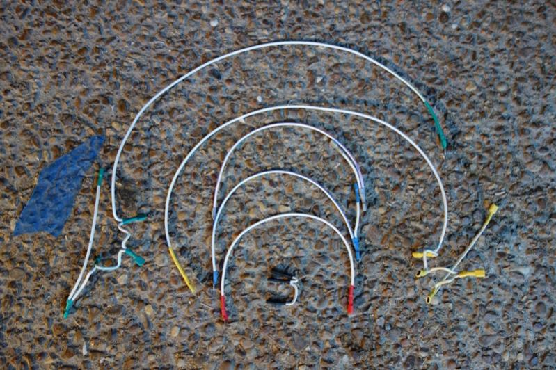
In order to provide feedback to and control of the fans from the cab, I chose to use lighted V-Series Contura switches from Carling Technologies. The switches you need are circuit “4” for the fan disable switch and circuit “6” for the engine fan switch. I used dual independent lights for both switches, lamp circuit U/Y (Circuit A/1 can be used for a single lighted fan disable switch). I sprung for LED lights and customized face plates, but these switches are also available in generic trim for significantly less money.
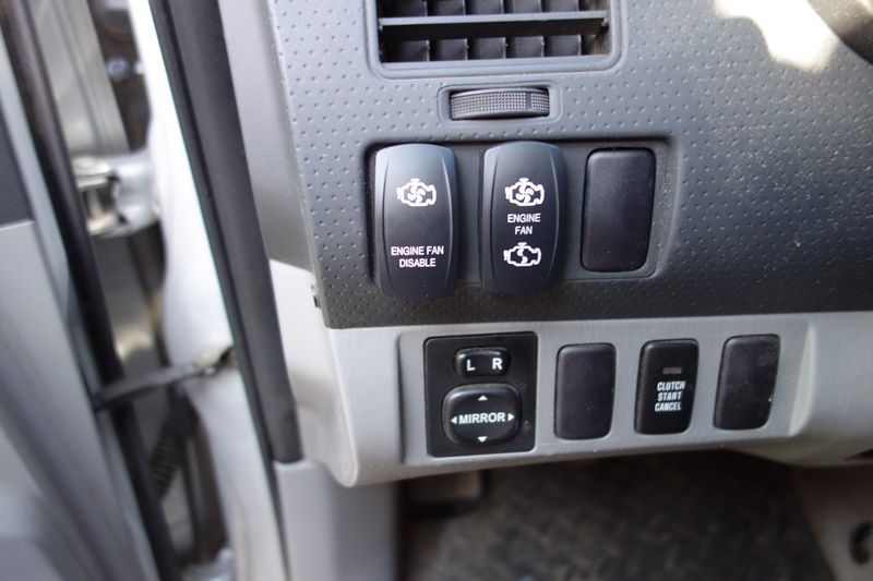
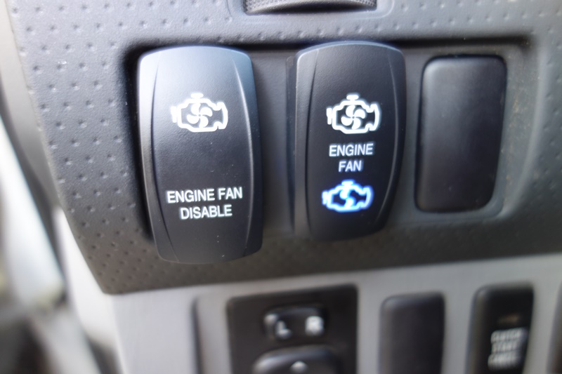
The fan disable switch is a two position switch which is unlit when on, but lights up red if you have the fans turned off. Typically this switch is left on and allows the power to flow from the accessory circuit to the fan relay triggers, but if you turn it off it diverts the power from the relay triggers to run the lights, thus without power the relays will not turn on, even if the ground triggers occur. The bright glowing red is the visual clue the system is bypassed, in case of accidentally bumping the switch.
The engine fan switch is a three position switch which lights up the bottom section blue when the fans are on low, and the top section blue when the fans are on high. It does this by using the fan relay low and high ground trigger wires connected to the grounds of the lights, which have power through the accessory circuit. If something triggers and grounds the relays, it will also ground the light which will then turn on. Additionally, you can press the switch to the top or bottom to override and turn the fans on low or high. It does this by manually grounding the appropriate low or high relay trigger, just like if the temperature switch had turned on. (Note: Manually pressing low will not override automatic high, this is by design.) These switches fit into factory spaces in the Tacoma, but you have to cut out a little of the plastic in the back part of the space.
 |
|
|
|
|
The Following 3 Users Say Thank You to aardvarcus For This Useful Post:
|
|
|
07-14-2015, 10:43 AM
|
#5 (permalink)
|
|
Master EcoModder
Join Date: Apr 2012
Location: Evensville, TN
Posts: 676
Thanks: 237
Thanked 580 Times in 322 Posts
|
Control Logic and Wiring:
I will post my schematic, but it is important to understand how the circuit works if you actually want to construct it. In order to be able to switch the fans in and out of parallel and series, three relays are required, two five pin and one four pin. The five pin relays have an output pin for both when the relay control circuit is off and when it is on. The four pin relays only have a pin for when the control circuit is on.
In a nutshell, you take the first fan and connect it's positive lead to the battery through a fuse. You take the second fan and connect its negative lead to a ground. Then you connect the other two leads of the fans to the switched input leads (pin 30) of the two five pin relays (not the control leads, not the output leads). The on output leads (pin 87) of the relays are connected where the first fan's relay connects it to ground when it is on, and the second fan's relay connects it to 12v through a fuse. Thus when these relays are turned on, both fans see a full voltage circuit as they are in parallel. Current flows in this order, battery positive terminal, fuse, Fan 1 + to -, fan 1 relay input through on output, and then to ground. Independently, current also battery positive terminal, fuse, fan 2 relay on output to input, Fan 2 + to -, and then to ground.
Now when both relays are turned off, neither fan is on, because the first has no ground and the second has no 12v power. However, through the use of the 5 pin relays, both of these relays connect their input pin to the off output pin (pin 87A). If you connect the input and on output pins (30 and 87) of the third relay to the two off output pins (pin 87A) of the first two relays, then when the third relay is turned on, it connects the circuit through both fans, where each fan sees half the voltage as they are in series. Following typical + to convention (not the electrons), current flows in this order, battery positive terminal, fuse, Fan 1 + to -, fan 1 relay input through off output, third relay through the input to the on output, fan 2 relay off output to input, Fan 2 + to -, and then to ground. Thus the fans can be switched from series to parallel. Trigger the third relay to turn them on low, and trigger the first two relays to turn them on high. Note the fans will turn on high regardless of the position of the third relay.
Since the RTMR is a five relay panel, and I only used four relays thus far, I hooked up an extra relay controlled fused accessory circuit. I also hooked up an extra always on fused accessory circuit.
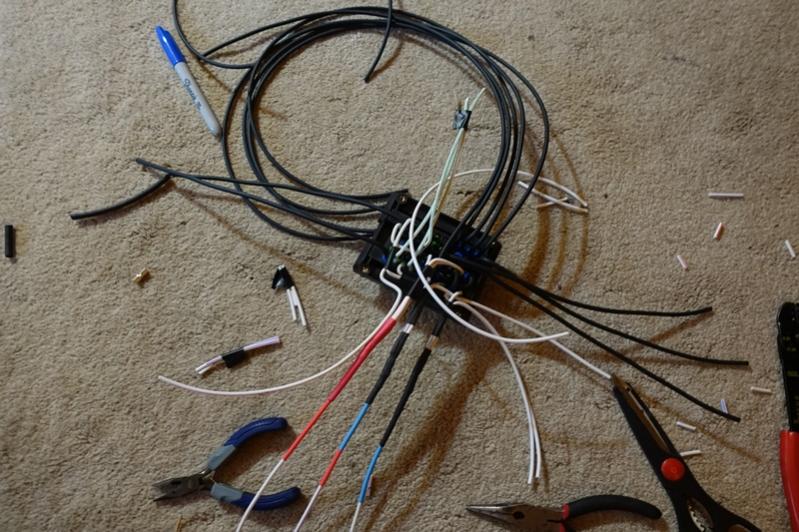
The only thing left is to just wire it all up! I attached two color coded excel files, these show how the wires go into the RTMR, too all the accessories, and how to hook up the switches in the cab.
 |
|
|
|
|
The Following 2 Users Say Thank You to aardvarcus For This Useful Post:
|
|
|
07-14-2015, 10:44 AM
|
#6 (permalink)
|
|
Master EcoModder
Join Date: Apr 2012
Location: Evensville, TN
Posts: 676
Thanks: 237
Thanked 580 Times in 322 Posts
|
Edit: 7/17/15 Finally Some Results
Ok, time for some results. I have very limited spare time and thus am unable to devote the time to do ABA testing so if you have read my other posts you know I look for changes over the course of tanks. I realize this is less scientific of a method, but it is all I got. To keep from unduely skewing results I usually put comments in my fuel log when a tank is very different than my usual routine, so that I can leave it out of any comparisons. These tanks are all everyday driving, none of these tanks are perfect by any stretch of the imagination.
I pulled data from my fuel log from about a month back, and threw out the fan changeover tanks (7/12) and two tanks because one was from a different pump (7/1) and then the other was using different fuel (7/6). All fills used below are the same gas station and same pump, and I ended up with seven mechanical fan tanks and three electric fan tanks. They are in my fuel log, but I copied them below.
Mechanical Fan
Date_____ Miles Gallons
6/10/2015 210.600 7.382
6/11/2015 148.512 5.044
6/15/2015 294.008 10.902
6/17/2015 245.752 8.684
6/22/2015 486.304 18.108
6/25/2015 293.280 10.44
7/09/2015 385.216 13.55
Total:___ 2063.672 74.11
Electric Fan
Date_____ Miles Gallons
7/14/2015 105.352 3.413
7/15/2015 185.016 6.411
7/17/2015 179.088 6.269
Total:___ 469.456 16.093
So dividing these figures out, this indicates the mechanical fan averaged me 27.846 MPG and the electric fan averaged me 29.171 MPG, or a 1.3 MPG or 4.76% improvement. This was roughly what I was expecting prior to the swap, so I am happy with the results. I will continue to monitor my MPG over the next few weeks; however I may be making some other changes to my truck in the near future.
I hope everyone enjoyed the read, and if you have any questions post them up.
Last edited by aardvarcus; 07-17-2015 at 07:10 AM..
Reason: Inserting some results.
|
|
|
|
|
The Following 4 Users Say Thank You to aardvarcus For This Useful Post:
|
|
|
07-14-2015, 10:54 PM
|
#7 (permalink)
|
|
EcoModding Lurker
Join Date: May 2015
Location: Madison, WI
Posts: 40
Thanks: 6
Thanked 23 Times in 8 Posts
|
Nice work. All I'm curious about is the fuel savings!
A friend of mine has been messing around with electric fans on his late model ford bronco for a while, and after several failed attempts, he now has it down pat. I'll ask him what components he is using soon.
|
|
|
|
|
07-15-2015, 04:48 PM
|
#8 (permalink)
|
|
Corporate imperialist
Join Date: Jul 2011
Location: NewMexico (USA)
Posts: 11,312
Thanks: 273
Thanked 3,583 Times in 2,845 Posts
|
I picked up 2mpg when I did the efan swap.
__________________
1984 chevy suburban, custom made 6.5L diesel turbocharged with a Garrett T76 and Holset HE351VE, 22:1 compression 13psi of intercooled boost.
1989 firebird mostly stock. Aside from the 6-speed manual trans, corvette gen 5 front brakes, 1LE drive shaft, 4th Gen disc brake fbody rear end.
2011 leaf SL, white, portable 240v CHAdeMO, trailer hitch, new batt as of 2014.
|
|
|
|
|
07-15-2015, 05:09 PM
|
#9 (permalink)
|
|
Master EcoModder
Join Date: Jun 2009
Location: SC Lowcountry
Posts: 1,796
Thanks: 226
Thanked 1,354 Times in 711 Posts
|
.
2002 Chevy 1500
Changed from clutch fan an to 16" electric fan.
Work's great...
I would recommend this Controller.
Flex-a-lite 31147 Electric Fan Temperature Switch
There has been a definite improvement in MPG. 
> |
|
|
|
|
07-15-2015, 07:32 PM
|
#10 (permalink)
|
|
.........................
Join Date: Aug 2009
Location: Buckley, WA
Posts: 1,597
Thanks: 391
Thanked 488 Times in 316 Posts
|
Nice write-up.
I was pleasantly surprised to see that this was well thought out and executed with a professional level of workmanship. A lot of these type of conversions are done quick and dirty and suffer from long-term reliability issues. I actually have the same controller that redneck posted in my classic pickup and have had leaks due to the temperature probe.
I like that Bussman fuse/relay box. I may have to use that for a few projects I have in mind.
|
|
|
|
|
The Following User Says Thank You to darcane For This Useful Post:
|
|
|