09-08-2011, 07:40 AM
|
#211 (permalink)
|
|
EcoModding Lurker
Join Date: Jul 2010
Location: South Africa
Posts: 85
Thanks: 9
Thanked 12 Times in 8 Posts
|
Ah, I understand (or at least I think I do - the 'rule').
However, the way I saw it, the slope in the rear of the cab didn't violate the shape or the respected drop-off angle(s), thus the Denali should in all fairness have attached flow at least as far as the C-pillar.
Thus if one then 'cheats' this ideal shape forward (to match the already gently sloping roof), the canopy/cap could loose another hand-width -or so- of height right at the back because the angles are all still good, Hence, this reduces the size of the wake, quite possibly still without the risk of detached flow compared to where the shape should 'ideally / per rules' sit.
Ignore this post if I'm just not getting it 
__________________

|
|
|

|
 Today Today
|
|
|
|
 Other popular topics in this forum...
|
|
|
|
|
09-08-2011, 08:24 AM
|
#212 (permalink)
|
|
Recreation Engineer
Join Date: Dec 2009
Location: Somewhere USA
Posts: 525
Thanks: 333
Thanked 138 Times in 103 Posts
|
Chaz makes an interesting point. The template suggests that truck may not support fully attached flow at the cab rear top. Seems like a good point to fact check with tuft testing. If flow there is attached, tangent the template. If not attached, obey the apex. The real goal is fully attached flow early and always. As least that's my understanding of the science behind the template.
|
|
|
|
|
09-08-2011, 12:03 PM
|
#213 (permalink)
|
|
Aero Deshi
Join Date: Jan 2010
Location: Vero Beach, FL
Posts: 1,065
Thanks: 430
Thanked 669 Times in 358 Posts
|
I will say this blasphemous statement once again, Attached Flow Is Not The Goal. There are plenty of times that flow is attached while far short of the design template. Just because it is attached, it does not mean the shape is optimal. There is NO DOUBT the flow is attached till the back portion of the roof on any pickup, it is the highest point of the truck, and the air density is very high here.
So what is the goal? I say it is to let the air which has been pushed up by the front of the truck, thus building density (not pressure, but density), re-expand or return to normal density while pressing down on the skin on the back of the vehicle, thus returning its energy.
We optimize this reclaiming of energy when we follow the template. If we drop a little quicker in the back, then the energy return (pressure) is not as great. If we drop quicker yet, there is still attached flow, but essentially no pressure at all returned. If we drop way too fast, then all hope is lost and a lot of turbulence is generated. Conversely, if we make the shape longer, then skin drag starts to become an issue.
Think of the air as a spring that gets compressed as we drive under it, and as we go past it, it is capable of releasing its energy back into the car. But if the shape is too fast, the spring is not able to keep up with it, and the energy is wasted.
Look at my thread here and I explain it a bit better (with diagrams). Let me know what you think.
Up & Down Aerodynamics |
|
|
|
|
The Following 2 Users Say Thank You to ChazInMT For This Useful Post:
|
dcb (09-08-2011), SvdM (01-09-2012) |
|
09-08-2011, 05:12 PM
|
#214 (permalink)
|
|
EcoModder
Join Date: Jul 2008
Location: North Central Alabama
Posts: 572
Thanks: 110
Thanked 123 Times in 71 Posts
|
Quote:
Originally Posted by ChazInMT

Attached Flow Is Not The Goal.
|
You are correct, drag reduction while maintaining usability is the goal.
Quote:
|
There are plenty of times that flow is attached while far short of the design template. Just because it is attached, it does not mean the shape is optimal.
|
Correct, air can stay attached up to about 30 degrees, which is great for keeping the rear windshield clean on lots of fastback cars, but terrible for their Cd!
Quote:
|
So what is the goal? I say it is to let the air which has been pushed up by the front of the truck, thus building density (not pressure, but density), re-expand or return to normal density while pressing down on the skin on the back of the vehicle, thus returning its energy.
|
You will never have 100% of the air that went over the top fill in the wake, no matter what template you use. The air is at a higher density and velocity than the air in the wake and wants to move toward that area (or any lower velocity / lower density area) through the path of least resistance. If that happens to be up, down, left, or right, that's where it will move. Much will fill in the wake area, and that's what we are trying to maximize.
Quote:
|
We optimize this reclaiming of energy when we follow the template.
|
Yes and no...
Yes, if you plan on taking your vehicle all the way out, following the template to completion, then yes, follow the template.
No, if you plan on cutting the vehicle anywhere short of the full template, use about a 12 degree angle. Hucho (and many others) have shown that for a truncated body, something like 10 or 12 degrees is the optimal for drag reduction. Granted, the tests done to generate these drag profile curves were done without making super smooth curves (like the template has), but they have been proven time and again to be about as good as you are going to get.
Look at these graphs, and ask yourself, where would the aerodynamic streamlining template have me be? Between 3.5 and 7.5 degrees? Following the logic above, this would be optimal, but it isn't... something more like 10 or 12 degrees wins the day.


Quote:
|
Conversely, if we make the shape longer, then skin drag starts to become an issue.
|
Not to mention having your super long boat tail smash into things when turning!
I checked out your other post (reminding me that velocity was involved... tisk tisk on me!) and I will be commenting once I am done reading.
__________________

Last edited by wyatt; 09-08-2011 at 06:10 PM..
Reason: Bernoulli - Pressure, Density, and Velocity... shame on me!
|
|
|
|
|
09-20-2011, 01:15 AM
|
#215 (permalink)
|
|
Master EcoModder
Join Date: Jan 2008
Location: Sanger,Texas,U.S.A.
Posts: 16,477
Thanks: 24,502
Thanked 7,436 Times in 4,817 Posts
|
cautionary note
Quote:
Originally Posted by wyatt
You are correct, drag reduction while maintaining usability is the goal.
Correct, air can stay attached up to about 30 degrees, which is great for keeping the rear windshield clean on lots of fastback cars, but terrible for their Cd!
You will never have 100% of the air that went over the top fill in the wake, no matter what template you use. The air is at a higher density and velocity than the air in the wake and wants to move toward that area (or any lower velocity / lower density area) through the path of least resistance. If that happens to be up, down, left, or right, that's where it will move. Much will fill in the wake area, and that's what we are trying to maximize.
Yes and no...
Yes, if you plan on taking your vehicle all the way out, following the template to completion, then yes, follow the template.
No, if you plan on cutting the vehicle anywhere short of the full template, use about a 12 degree angle. Hucho (and many others) have shown that for a truncated body, something like 10 or 12 degrees is the optimal for drag reduction. Granted, the tests done to generate these drag profile curves were done without making super smooth curves (like the template has), but they have been proven time and again to be about as good as you are going to get.
Look at these graphs, and ask yourself, where would the aerodynamic streamlining template have me be? Between 3.5 and 7.5 degrees? Following the logic above, this would be optimal, but it isn't... something more like 10 or 12 degrees wins the day.
Not to mention having your super long boat tail smash into things when turning!
I checked out your other post (reminding me that velocity was involved... tisk tisk on me!) and I will be commenting once I am done reading. |
I just wanted to throw a cautionary flag on the play.The model used to develop the tabulated data lacks side body camber,tumblehome,and edge radii,all necessary for lowest drag.
While the data in the table reflect minimums for the 'model',they might not reflect what is best for a more sophisticated architecture in the wind tunnel.
Since the 'Template' is generated from a streamlined body of revolution,it does embody plan taper,tumblehome,and edge radii,hence reflects a best-case scenario,perhaps bested only by the Morelli form. Each member will want to investigate how easily the Morelli form could be applied to their vehicle for the purposes of streamlining.
|
|
|
|
|
The Following User Says Thank You to aerohead For This Useful Post:
|
|
|
09-29-2011, 07:49 AM
|
#216 (permalink)
|
|
Master EcoModder
Join Date: Jul 2011
Location: Ann Arbor, Michigan
Posts: 4,208
Thanks: 140
Thanked 2,824 Times in 1,981 Posts
|
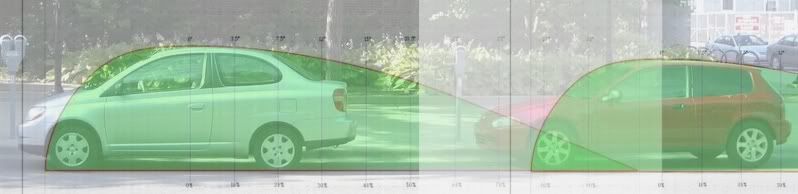
I overlaid the template over a photo I took a couple of years ago. It's an odd image in that the two cars are at least 20 years apart, and represent different thinking/marketing/packaging.
Automobile pictures by kach22i - Photobucket
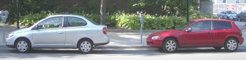
I did not know where else to post this, this is as good as any place, right?
I think the older red car does a better job of fitting the template.
EDIT: Would this fit the template?
http://forums.pelicanparts.com/off-t...tures-597.html

__________________
George
Architect, Artist and Designer of Objects
2012 Infiniti G37X Coupe
1977 Porsche 911s Targa
1998 Chevy S-10 Pick-Up truck
1989 Scat II HP Hovercraft
You cannot sell aerodynamics in a can............
Last edited by kach22i; 09-29-2011 at 12:09 PM..
|
|
|
|
|
10-08-2011, 03:16 PM
|
#217 (permalink)
|
|
Master EcoModder
Join Date: Jan 2008
Location: Sanger,Texas,U.S.A.
Posts: 16,477
Thanks: 24,502
Thanked 7,436 Times in 4,817 Posts
|
'motohome'
Quote:
Originally Posted by kach22i
|
I think that in this instance,the designer was interested in shunting most of the air around the sides than over the top and is probably relying on symmetrical strut sections as the inspiration.Just guessing.
|
|
|
|
|
10-09-2011, 09:07 AM
|
#218 (permalink)
|
|
EcoModding Apprentice
Join Date: Jan 2008
Location: Mid TN
Posts: 152
Thanks: 4
Thanked 2 Times in 2 Posts
|
Quote:
Originally Posted by kach22i
|
It looks like those struts on top are actually hand rails for some steps. It almost looks like a steering wheel and a bench seat up top in that pic.
Looks almost like an open command center on top...Very interesting...does anybody know what name to search for to get more pics of this beast???
__________________

|
|
|
|
|
10-09-2011, 10:03 PM
|
#219 (permalink)
|
|
EcoModding Lurker
Join Date: May 2011
Location: WA
Posts: 10
Thanks: 0
Thanked 4 Times in 4 Posts
|
blastolene.com/Work_in_Progress/deco.htm
The Decoliner
|
|
|
|
|
10-11-2011, 07:44 PM
|
#220 (permalink)
|
|
Banned
Join Date: Oct 2009
Location: Fort Worth, Texas
Posts: 2,442
Thanks: 1,422
Thanked 737 Times in 557 Posts
|
FWD GMC motorhome pinnings. An art car.
|
|
|
|
|