Go Back   EcoModder Forum > EcoModding > Aerodynamics
Register Now
 Register Now
 

Reply  Post New Thread
 
Submit Tools LinkBack Thread Tools
Old 05-31-2013, 02:38 AM   #551 (permalink)
EcoModding Lurker
 
betasniper's Avatar
 
Join Date: Feb 2013
Location: California
Posts: 79

Red - '01 Honda Insight CVT
Gen-1 Insights
House of Tudor
Team Honda
90 day: 59.17 mpg (US)

Civic Hybrid - '12 Honda Civic Hybrid
Team Honda

Bahamut - '18 Chevrolet Volt LT
Team Volt
Plug-in Hybrids
Thanks: 6
Thanked 48 Times in 23 Posts
Quote:
Originally Posted by aerohead View Post
I would compare it to Mair's boat tail.
He used about one body diameter length to curve his body into a 22-degree slope,and then just maintained a constant slope as in your rendering.
The 'straight' conical sections are easier to fabricate but must be reinforced from the inside,as they have no eggshell strength of the compound curve and will 'tin can'.
Yeah, It was about a 15° angle at the end for that one because the thickness was only 35% (Eppler 863). I posted that airfoil because that was the largest symmetric airfoil I found in that database. There is a very slightly unsymmetric airfoil which is a 38.8% thickness (Eppler 864), but even that one only goes to an 18° angle.

I put the AST-2 Template into Solidworks and tried as best as I could to make a simple spline fit the Template but These are the angles I got:

Largest deviation (angle wise) was the very first angle with a 1.3° discrepancy. Everything else is within .4°. The grey dimensions are driven and Σ's are equations. Only the black Numbers without Σ can be altered (The 500 and the 23°). The blue lines above the spline represent the curvature. Bigger lines means more curve, Smaller lines means flatter.

Edit: Even though the angle discrepancy is large, the spline I drew was slightly slower curve than the template. Very slight.
Code:
Percentage
0%
10%
20%
30%
40%
50%
60%
70%
80%
90%
100%
X
0
172
344
516
688
860
1032
1204
1376
1548
1720
Y
500.00
488.92
461.69
423.61
377.54
325.23
267.81
206.09
140.62
71.81
0
Angle
6.8°
10.9°
13.9°
16.0°
17.7°
19.1°
20.3°
21.3°
22.2°
23.0°

Attached Thumbnails
Click image for larger version

Name:	AST 2 Dimensions.jpg
Views:	1235
Size:	143.2 KB
ID:	13123  
__________________

: Brothers
: Dad's

Last edited by betasniper; 05-31-2013 at 03:03 AM..
  Reply With Quote
The Following 3 Users Say Thank You to betasniper For This Useful Post:
aerohead (06-01-2013), BamZipPow (05-31-2013), ChazInMT (05-31-2013)
Alt Today
Popular topics

Other popular topics in this forum...

   
Old 05-31-2013, 03:05 PM   #552 (permalink)
Aero Deshi
 
ChazInMT's Avatar
 
Join Date: Jan 2010
Location: Vero Beach, FL
Posts: 1,065

MagMetalCivic - '04 Honda Civic Sedan EX
Last 3: 34.25 mpg (US)
Thanks: 430
Thanked 668 Times in 357 Posts
Thanks Betasniper, I went and looked at the drawing again and realized it was still a little lumpy and didn't quite match Aeroheads drawing as closely as I thought. So I tweaked it again and now have a very exact match to what Aerohead drew.

I'm going to go update the "flawed" image in previous posts with this one, so if you're linked to the old-new version (?) it will prolly yield a blank now.

Here is the small version.


And here's the HiRes large one. (If you haven't figured out....ecomodder, great as it is, is somewhat limited in the resolution of the pictures that can be displayed. Which is why I have been putting everything on TinyPic and then just linking to it)
  Reply With Quote
The Following 2 Users Say Thank You to ChazInMT For This Useful Post:
aerohead (06-01-2013), betasniper (05-31-2013)
Old 05-31-2013, 04:21 PM   #553 (permalink)
EcoModding Lurker
 
betasniper's Avatar
 
Join Date: Feb 2013
Location: California
Posts: 79

Red - '01 Honda Insight CVT
Gen-1 Insights
House of Tudor
Team Honda
90 day: 59.17 mpg (US)

Civic Hybrid - '12 Honda Civic Hybrid
Team Honda

Bahamut - '18 Chevrolet Volt LT
Team Volt
Plug-in Hybrids
Thanks: 6
Thanked 48 Times in 23 Posts
Here is a spline fitted to Aerohead's straightened drawing:

His hand drawn curve is very "ideal" as a spline actually.
Angles match pretty well with what you posted.

The New numbers on the ends are the lengths of the driving handles.
Attached Thumbnails
Click image for larger version

Name:	AST 2 Dims.jpg
Views:	1199
Size:	143.2 KB
ID:	13126  
__________________

: Brothers
: Dad's
  Reply With Quote
The Following 3 Users Say Thank You to betasniper For This Useful Post:
aerohead (06-01-2013), BamZipPow (05-31-2013), ChazInMT (05-31-2013)
Old 05-31-2013, 07:04 PM   #554 (permalink)
Aero Deshi
 
ChazInMT's Avatar
 
Join Date: Jan 2010
Location: Vero Beach, FL
Posts: 1,065

MagMetalCivic - '04 Honda Civic Sedan EX
Last 3: 34.25 mpg (US)
Thanks: 430
Thanked 668 Times in 357 Posts
Quote:
Originally Posted by betasniper View Post
His hand drawn curve is very "ideal" as a spline actually.
I know, Right. I kept sayin that as I was tracing it. Phil Rocks it Old School!
  Reply With Quote
Old 05-31-2013, 07:43 PM   #555 (permalink)
Master EcoModder
 
kach22i's Avatar
 
Join Date: Jul 2011
Location: Ann Arbor, Michigan
Posts: 4,158
Thanks: 120
Thanked 2,790 Times in 1,959 Posts
FYI: pages 24-30-ish have several post by ERTW, which is the missing link several people remembered but could not locate.

http://ecomodder.com/forum/showthrea...c-9287-24.html

http://ecomodder.com/forum/showthrea...c-9287-25.html


http://ecomodder.com/forum/showthrea...c-9287-26.html


More than one person expressed misgivings about the template's application and usefulness other than in the abstract. I am not alone on that one.

The below overlays based ERTW's work, but I don't have his 3D skills/programs. They should get the point across though.

Automobile 2 - Odds And Ends Photos by kach22i | Photobucket


A different fitting attempt to convey the message.


Close up detail


So what do we do about a square peg trying to fit into a semi-circular hole?
__________________
George
Architect, Artist and Designer of Objects

1977 Porsche 911s Targa
1998 Chevy S-10 Pick-Up truck
1989 Scat II HP Hovercraft

Chin Spoiler:
http://forums.pelicanparts.com/off-t...effective.html

Rear Spoiler Pick Up Truck
http://forums.pelicanparts.com/off-t...xperiment.html

Roof Wing
http://ecomodder.com/forum/showthrea...1-a-19525.html
  Reply With Quote
The Following User Says Thank You to kach22i For This Useful Post:
aerohead (03-12-2016)
Old 05-31-2013, 07:59 PM   #556 (permalink)
EcoModding Lurker
 
betasniper's Avatar
 
Join Date: Feb 2013
Location: California
Posts: 79

Red - '01 Honda Insight CVT
Gen-1 Insights
House of Tudor
Team Honda
90 day: 59.17 mpg (US)

Civic Hybrid - '12 Honda Civic Hybrid
Team Honda

Bahamut - '18 Chevrolet Volt LT
Team Volt
Plug-in Hybrids
Thanks: 6
Thanked 48 Times in 23 Posts
See Tesla's post:
Quote:
Originally Posted by Tesla View Post
For his words, click up here^


And a fitting to a typical car:
__________________

: Brothers
: Dad's
  Reply With Quote
The Following User Says Thank You to betasniper For This Useful Post:
aerohead (03-12-2016)
Old 06-01-2013, 10:26 AM   #557 (permalink)
Master EcoModder
 
kach22i's Avatar
 
Join Date: Jul 2011
Location: Ann Arbor, Michigan
Posts: 4,158
Thanks: 120
Thanked 2,790 Times in 1,959 Posts
Quote:
Originally Posted by betasniper View Post
See Tesla's post:
My point exactly, there is no longitudinal section template for going from square to round, and there is no plan template for going from square to round. Therefore using the Part-C template for these purposes is completely misguided and in error.

Post #463
http://ecomodder.com/forum/showthrea...c-9287-47.html
Quote:
Originally Posted by Tesla View Post
.....................

I first did a rough hemisphere to test the calculations, my co ordinates are not perfect, (hence the rough inner plots), but it does show regular increasing reduction as one would expect of half a teardrop form, chart below:


Then I punched in a set of coordinates for a square, to represent a basic vehicle profile, y crosses x at 0 (ground level), chart below:


What it does show is that the corners, being a diagonal profile are further from the focal point, hence their rate of taper is reduced, but the sides at ground level have the shortest length and the most aggressive change.

I am begining to doubt the narrowest dimension rule, this diagonal effect, for me seems to give some explanation why the whole square vehicle is so bad aerodynamically, because it is very difficult to get those corners together without seperation occuring............................

I'm sure there are many other things that come into play and no vehicle is completely square, but it does highlight the potential issues with corners being too aggressive in taper, and if looking for a vehicle to aero customize, it's worth paying more attention to the curvature of the frontal cross section, if it is really square, that will work against you more than if it is more circular.
The study of going from square to round and the drag creating vortexes which may result are far more relevant to boattailing than the hemispherical sectioned template Part-C .....in my humble opinion.

The template as first introduced as I understand it was meant to be used as a template for creating boattails on existing automobiles (I've already quoted aerohead recently on this).

However as shown in the cross section study I did, adaption from square to round is not even a consideration. This could be an extreme oversight, or not a big deal (see Tesla's comments), the more I think about it, the more I see need for a remedy.

My contention is that square does not fit round, it should not be a "hard-sell", it should sell it's self.

Proposal: Two new templates need to be developed in 3D (eighty or ninety percent length?)
Industrial Design - Transportation Photos by kach22i | Photobucket


Tesla's post #400 is very interesting, describes the conditions but no plan template. The sides will come in quicker than the roof. Is that anything like re-scaling the template for different lengths and conditions?

Link:
http://ecomodder.com/forum/showthrea...c-9287-40.html

http://s184.photobucket.com/user/kac...?sort=3&page=1


Conclusion: We need at least a new plan template showing the more aggressive truncation.

Then we need several 3D models to fit typical situations.

Then we need at CFD models/videos/stills and testing to examine the airflow and possible vortexes to take it to the next level. That being full scale models/projects and wind-tunnel testing to verify.
__________________
George
Architect, Artist and Designer of Objects

1977 Porsche 911s Targa
1998 Chevy S-10 Pick-Up truck
1989 Scat II HP Hovercraft

Chin Spoiler:
http://forums.pelicanparts.com/off-t...effective.html

Rear Spoiler Pick Up Truck
http://forums.pelicanparts.com/off-t...xperiment.html

Roof Wing
http://ecomodder.com/forum/showthrea...1-a-19525.html

Last edited by kach22i; 06-01-2013 at 10:54 AM..
  Reply With Quote
Old 06-01-2013, 01:49 PM   #558 (permalink)
Master EcoModder
 
aerohead's Avatar
 
Join Date: Jan 2008
Location: Sanger,Texas,U.S.A.
Posts: 15,895
Thanks: 23,972
Thanked 7,223 Times in 4,650 Posts
help

Quote:
Originally Posted by freebeard View Post
Bless you. Do this:
My ability to help you ends there.
Thanks freebeard! I'll chip away at it.
__________________
Photobucket album: http://s1271.photobucket.com/albums/jj622/aerohead2/
  Reply With Quote
Old 06-01-2013, 03:00 PM   #559 (permalink)
Master EcoModder
 
aerohead's Avatar
 
Join Date: Jan 2008
Location: Sanger,Texas,U.S.A.
Posts: 15,895
Thanks: 23,972
Thanked 7,223 Times in 4,650 Posts
common conditions

Quote:
Originally Posted by kach22i View Post
FYI: pages 24-30-ish have several post by ERTW, which is the missing link several people remembered but could not locate.

http://ecomodder.com/forum/showthrea...c-9287-24.html

http://ecomodder.com/forum/showthrea...c-9287-25.html


http://ecomodder.com/forum/showthrea...c-9287-26.html


More than one person expressed misgivings about the template's application and usefulness other than in the abstract. I am not alone on that one.

The below overlays based ERTW's work, but I don't have his 3D skills/programs. They should get the point across though.

Automobile 2 - Odds And Ends Photos by kach22i | Photobucket


A different fitting attempt to convey the message.


Close up detail


So what do we do about a square peg trying to fit into a semi-circular hole?
*If you're working with a production car ignore the variance between the vehicle's outer surface architecture and that of the outer surface of the Template's 'revolution' at all vantage points radial to the polar axis of the ground plane centerline.
*In elevation,your roofline would follow the 'Template' as depicted.
*In plan-view,for the sides of the car,you would attempt to take this same profile from the roof and do a best-fit based upon the existing body camber.
*Since the body will have both vertical camber and tumblehome (when viewed from front or rear) the profile is brought into contact along flanks and greenhouse in a best-fit with the alignment based radially to the polar axis.
*Since most vehicles are defined by character lines,the body will be treated as cambered panels (as GM has done with their VOLT) and the original seams,edges and radii can be maintained as the body is generated rearwards,contracting as it projects,at no greater rate than with the half-body.
*One panel may no doubt 'force' a geometric compromise with adjoining panels and in this situation you must 'morph' the panel intersection such that it does not violate the 'Template' profile based on it's radial position with the polar axis.
--------------------------------------------------------------------------
It's easier to fabricate than it is to describe.
*My CRX is an example.
*The T-100 another.
*You can see it in the AeroCivic.
*MetroMPG's Geo Metro boat tail
*3Wheeler's Insight boat tail
*MetroMPG's Insight tail in progress.
*JetroBodine's Rabbit boat tail
*The Matrix/Vibes that have been done ay EcoModder
*Redneck's Metro is the most recent example.
-------------------------------------------------------------------------
Actual 'Template' research/LSR/Solar/etc. vehicles would be:
*Jaray's original pumpkin seed of 1921.
*Lay's models of 1933
*Elliott Reid's circa '34
*Heald's circa '34
*Fachsenfeld's of 1936
*the Schl'o'r car of 1937
*MG EX 181 of '57
*Mickey Thompson's 'pumpkinseed' circa 1961
*W.A.Mair's work creates a fine 'Template' when the constant-velocity portion of the model is removed,1968.
*R.G.S.White's,MIRA composite Cd 0.245 car model is not a bad 'Template' for 1968.
*D-B,M-B C-111 III,1978
*GM/AeroVironment SunRaycer,1987
*Chevy 'Express',1987
*Renault Vesta II,1987
*M-B 'Boxfish
*VW XL1,2012
*World Solar GT,Bochum University,2012
*CUER,Cambridge University,World Solar Challenge,2013
There are some others but my work books are in the cab of the truck,14-miles from here.
__________________
Photobucket album: http://s1271.photobucket.com/albums/jj622/aerohead2/
  Reply With Quote
Old 06-01-2013, 03:48 PM   #560 (permalink)
Master EcoModder
 
aerohead's Avatar
 
Join Date: Jan 2008
Location: Sanger,Texas,U.S.A.
Posts: 15,895
Thanks: 23,972
Thanked 7,223 Times in 4,650 Posts
Testing

Wind tunnel testing for the 'Template' was originally conducted by Wolfgang Klemperer in 1921 at the Zeppelin Werkes.
It's been re-tested by various aerodynamicists throughout the decades since,including Hucho.
This 'original' 'Template' is the Jaray half-body,derived from an airship hull.
--------------------------------------------------------------------------
Hucho uses Jaray's roof contour as a benchmark for boundary layer integrity and separation-free,attached laminar flow.
--------------------------------------------------------------------------
Roof contours steeper than Jaray's roofline are what Hucho refers to as 'pseudo-jaray'.These roof contours produce separation and very strong attached longitudinal vortices of remarkably high drag.
--------------------------------------------------------------------------
The 2.5:1 'teardrop' from which the AST-I&II are derived are well-tested and produce Cd 0.04.
--------------------------------------------------------------------------
The 5:1(effective fineness ration) half-body derived from the teardrop is well-tested and produces a body of Cd 0.08 in ground proximity.
--------------------------------------------------------------------------
When wheels.tires are added to the half-body,the drag increases to Cd 0.12-13,depending on tire width.This has been well-tested.
-------------------------------------------------------------------------
When wheel fairings are employed,the drag can fall well below Cd 0.12.This is well-tested.
-------------------------------------------------------------------------
-------------------------------------------------------------------------
In light of the fact that so much testing and re-verification testing has been accomplished since 1921,it's extremely unlikely that the aerodynamicists involved have missed anything significant.And so,the 'Template' could pass for off-the-shelf technology,nothing theoretical about it anymore.Just waiting to be exploited.
------------------------------------------------------------------------
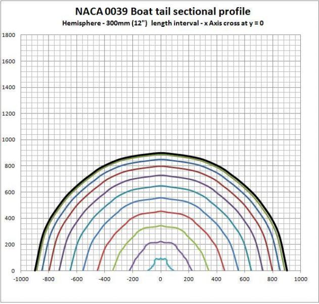
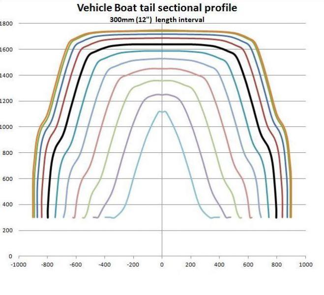
Any members with Hucho's book(s) will already know that he'll tell you that there a plenty of ways to get to Cd 0.15.If you want to go any lower,then you must extend the back of the body,while reducing its cross-sectional area such as not to produce separation.And Jaray's profile guarantees success here.
------------------------------------------------------------------------
Of course,no production car is circular in cross-section.They don't need to be.As long as any elongation of the body produces only the progressive reduction in cross-sectional area as with the 'Template' there shouldn't be any separation,nor vorticity of any significance.It's structurally impossible.Sectional density is respected to the highest degree.
----------------------------------------------------------------------
And so it's my humble opinion,that we've had enough testing.We've tested the thing to death.And it always delivers the lowest drag (for a car you can walk up to,open a door,and get in or out of,without a bunch of teammates to help).

__________________
Photobucket album: http://s1271.photobucket.com/albums/jj622/aerohead2/
  Reply With Quote
The Following User Says Thank You to aerohead For This Useful Post:
jime57 (06-02-2013)
Reply  Post New Thread


Similar Threads
Thread Thread Starter Forum Replies Last Post
Maximum angle for boat tail? abcdpeterson Aerodynamics 80 11-03-2021 12:55 PM
Aerodynamic Streamlining Template Part-B aerohead Aerodynamics 8 05-31-2013 12:23 PM
LED Headlight captainslug DIY / How-to 82 11-15-2011 01:32 AM
Aerodynamic Streamlining Template: Part-A aerohead Aerodynamics 0 07-18-2009 02:37 PM
All items I scanned in the new product showcase dremd The Lounge 0 11-08-2008 04:14 PM


Powered by vBulletin® Version 3.8.11
Copyright ©2000 - 2024, vBulletin Solutions Inc.
Content Relevant URLs by vBSEO 3.5.2
All content copyright EcoModder.com