 10-18-2014, 04:54 PM
|
#1241 (permalink)
|
|
Permanent Apprentice
Join Date: Jul 2010
Location: norcal oosae
Posts: 523
Thanks: 351
Thanked 318 Times in 215 Posts
|
Quote:
Originally Posted by MPaulHolmes

Could you post a picture of the layout and where the connector is? That would help me get the creative juices flowing. haha
cts_casemod: I have 1 more board, but I was going to populate it for testing. The other 4 boards are prototypes of people on here. Also, it's going to need a revision, so I'll have to order more once we figure out what needs changing.
|
Hi Paul!
Here's a pic of the board:
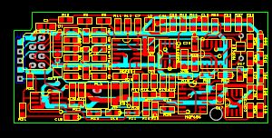
The five pin SIL connector is on the bottom of the board and fits the QEI connector. Because of the fastening issues, it would be nice to find a latching board-board connector. 
The 8 pin connector right next to it is on top, and is a latching flat-ribbon wire connector, designed for standard 0.05" spaced wires. I figure eventually this controller will be in some form of box, where it can connect to a shielded cable. I have an 8 connector shielded wire to see how that will work out. There are 3 pairs of wires for the resolver, and two for the motor's thermistor. The motor's thermistor connects to the QEI index pin.
The two pin connector is a latching connector for the +24V supply.
The notch on the upper left of the board is clearance for the POT connector.
Right now there is one bolt hole, on the bottom right of the board. There is no other place on the motor controller to put a hole. I probably could shuffle stuff around more to make space for a second hole right above it.
OK - requests for the second rev controller board:
1) Provisions for a latching QEI connector - I haven't found one yet.
2) Provisions for a second fastening hole for the resolver board
3) Some way to seperate the driver boards from the controller board to allow IGBT versatility.
Please - anyone - RIP on this board - I would much rather hear of it's issues now, then when it's done.
My biggest concern is noise. This board will sit right over the microprocessor and the microprocessor's timing crystal. Also, it will have it's own noise generator, a 50kHz oscillator.
If anyone has had any experience with these interactions, I would love to here it. Also, on the lower left side of the board is the output amplifier. It was designed for about 2 sq. inches of bare copper to act as a heat sink. I obviously don't have that, and need to come up with some decent alternative.
E*clipse
|
|
|

|
|
The Following User Says Thank You to e*clipse For This Useful Post:
|
|
 Today Today
|
|
|
|
 Other popular topics in this forum...
|
|
|
|
|
10-18-2014, 05:07 PM
|
#1242 (permalink)
|
|
EcoModding Apprentice
Join Date: Nov 2012
Location: East Midlands
Posts: 180
Thanks: 13
Thanked 81 Times in 52 Posts
|
Quote:
Originally Posted by e*clipse
Hi Paul!
Here's a pic of the board:
Please - anyone - RIP on this board - I would much rather hear of it's issues now, then when it's done.
My biggest concern is noise. This board will sit right over the microprocessor and the microprocessor's timing crystal. Also, it will have it's own noise generator, a 50kHz oscillator.
If anyone has had any experience with these interactions, I would love to here it. Also, on the lower left side of the board is the output amplifier. It was designed for about 2 sq. inches of bare copper to act as a heat sink. I obviously don't have that, and need to come up with some decent alternative.
E*clipse
|
I can see your bottom layer (?), the blue, is not very populated. It could be a good idea to fill the empty space with a ground plane/grid. Also where the regulator will be, use a few vias, to help reduce the thermal resistance and dissipate heat to the bottom layer. The same is valid for the output amplifier.
Mounting:
There are components very close to the mounting hole. It may happen that if you put a screw on there its head will either touch or squash some.
If I may suggest, if you use a ground plane you could leave some exposed copper to solder some metallic adapter where the screw could safely seat. |
|
|
|
|
10-18-2014, 06:03 PM
|
#1243 (permalink)
|
|
Permanent Apprentice
Join Date: Jul 2010
Location: norcal oosae
Posts: 523
Thanks: 351
Thanked 318 Times in 215 Posts
|
Quote:
Originally Posted by cts_casemod
I can see your bottom layer (?), the blue, is not very populated. It could be a good idea to fill the empty space with a ground plane/grid. Also where the regulator will be, use a few vias, to help reduce the thermal resistance and dissipate heat to the bottom layer. The same is valid for the output amplifier.
Mounting:
There are components very close to the mounting hole. It may happen that if you put a screw on there its head will either touch or squash some.
If I may suggest, if you use a ground plane you could leave some exposed copper to solder some metallic adapter where the screw could safely seat.
|
cts_casemod,
Thanks for the suggestions!
Yes, the bottom layer - I'm trying to make this a 2 layer design - is primarily the ground, +5V supply and a few signal lines. The boards output to the mainboard run on the bottom - I'm not happy with that because of the proximity to noisy stuff. 
If I make the board a 4 layer board, there will be plenty of room for a ground plane and even a bottom layer heatsink. Maybe it's worth it just to pay the extra $$$.
Regarding the mounting hole - yes; I'm working on that. Right I'm generally unhappy with it because of that spacing issue and because it needs to be a relatively small (3mm) bolt that's made of some non conductive material. The reason for this is the matching hole on the motor controller will have to fit in that space between the controller and driver boards. I want to make sure that the fastener isn't the cause for any shorting situations.
I really like the idea of using the heatsink for a fastener - I'll see what I can do there. A relatively large, thick piece of copper would be great for this. BTW, the thermal loading on the output amplifier is pretty constant. Actually the quiescent current (just running the IC, not amplifying anything) is the primary load.
Two questions regarding grounds:
On this board, there are actually two grounds - One for the +24V supply and one for the +5V supply (with is the majority of the board) Is there an issue with connecting the two grounds? Should I put a resistor or some protection device between them?
If I make a ground plane, out of the ground connections (half of the thick blue traces) and the remaining board space, what's the possibility of this becoming a noise "antenna"? How much space should I leave between signal traces and this ground? (for noise issues).
Thanks again,
E*clipse |
|
|
|
|
10-18-2014, 06:22 PM
|
#1244 (permalink)
|
|
EcoModding Apprentice
Join Date: Nov 2012
Location: East Midlands
Posts: 180
Thanks: 13
Thanked 81 Times in 52 Posts
|
Quote:
Originally Posted by e*clipse
cts_casemod,
Thanks for the suggestions!
Yes, the bottom layer - I'm trying to make this a 2 layer design - is primarily the ground, +5V supply and a few signal lines. The boards output to the mainboard run on the bottom - I'm not happy with that because of the proximity to noisy stuff.
If I make the board a 4 layer board, there will be plenty of room for a ground plane and even a bottom layer heatsink. Maybe it's worth it just to pay the extra $$$.
Regarding the mounting hole - yes; I'm working on that. Right I'm generally unhappy with it because of that spacing issue and because it needs to be a relatively small (3mm) bolt that's made of some non conductive material. The reason for this is the matching hole on the motor controller will have to fit in that space between the controller and driver boards. I want to make sure that the fastener isn't the cause for any shorting situations.
I really like the idea of using the heatsink for a fastener - I'll see what I can do there. A relatively large, thick piece of copper would be great for this. BTW, the thermal loading on the output amplifier is pretty constant. Actually the quiescent current (just running the IC, not amplifying anything) is the primary load.
Two questions regarding grounds:
On this board, there are actually two grounds - One for the +24V supply and one for the +5V supply (with is the majority of the board) Is there an issue with connecting the two grounds? Should I put a resistor or some protection device between them?
If I make a ground plane, out of the ground connections (half of the thick blue traces) and the remaining board space, what's the possibility of this becoming a noise "antenna"? How much space should I leave between signal traces and this ground? (for noise issues).
Thanks again,
E*clipse |
Typically the grounds are isolated in the following conditions:
Current measurement;
Galvanic isolation;
Analog and digital logic;
I assume the first is N/A here, so ask yourself if you need electrical isolation. If not, a single ground would be better at shielding noise, that two separate.
The last one is analog and digital logic. I assume most of it is digital, so wont imagine many conflicts there, but review as I am not completely familiar with the design. Generally tough, if this is the case, the positive is isolated instead trough a low value 4.7R resistor or an inductor to cut HF noise, along with some nice, low ESR, ceramic decoupling capacitors.
Isn't the board close to the motor? If so grounding the motor will automatically create a "Faraday cage effect" and better yet if you share both grounds (motor + PCB + Vehicle) unless the board needs electrical isolation, but this is another issue you should avoid, because again, if the GND is shared with the vehicle it will work for you at cleaning noise rather than being an antenna, not to mention the risk for an isolated system if a cable gets caught and makes contact with some path in the vehicle, effectively breaking the isolation barrier.
Ground should be as close as possible to your signals. The larger the gap, the larger the airgap and generally the more coupling (noise) from nearby conductors
Copper pour - Wikipedia, the free encyclopedia |
|
|
|
|
The Following User Says Thank You to cts_casemod For This Useful Post:
|
|
|
10-19-2014, 04:00 PM
|
#1245 (permalink)
|
|
Permanent Apprentice
Join Date: Jul 2010
Location: norcal oosae
Posts: 523
Thanks: 351
Thanked 318 Times in 215 Posts
|
cts_casemod,
This is actually a primarily high frequency (RF) analog circuit.
A 50kHz sin wave starts out as a 50kHz square wave in the oscillator on the lower right corner of the board. Signal conditioning in the quad op-amp to the left of the oscillator converts this to two 180 degree out of phase sin waves that are amplified to about 7V p-p in the final amplifiers on the lower left of the board. All this provides the 14V p-p 50kHz sine wave carrier signal for the resolver.
The signals return from the resolver in the form of 50kHz sin and cosine waves in the plug on the upper left corner of the board. (along with the reference signal and the motor temperature signal.) These signals are filtered and amplified with the quad op amp to the plug's right. To the op amp's right is an analog switch that saves just the peaks of the carrier signals. It's triggered by the original 50kHz signal that is delayed and shaped by the quad op amp on the upper-right corner of the board. This op-amp also amplifies and offsets the final output signals, which are sin and cos waves with a frequency 2X the motor rpm. These signal are finally sent out in the 5pin SIL connector on the upper left of the board.
Anyway, as you can see, it's a primarily RF analog circuit.
A lot of my noise paranoia is coming from the app-note that accompanied the output amplifier (the one on the lower left of the board) It HIGHLY recommended AGAINST having any ground plane directly underneith the input and output pins. Also, when considering noise, this board (and possibly the ground plane) will be directly above the microcontroller and it's clock, which are sending out noise at about 30 MIPs in addition to Paul having noise problems at about 125kHz.
My circuit is fairly robust, and shouldn't have weird resonant issues due to this noise, however, it will be sending a critical signal, then filtering/amplifying it. If I can avoid pulling in extra noise or perhaps have a good way of filtering it out, it would make things much better for the AtoD converter in the end.
Regarding power conditioning:
Each IC has at least a 0.1uF ceramic capacitor. IC's that are physically really close share a 0.22uF ceramic capacitor. The final output amp uses both a 1uF ceramic capacitor and a 0.1uF ceramic capacitor.
Both the +5V and +24V inputs use a 10uF ceramic capacitor and a TVS in parallel. Here is where a ferrite or a small 4.7 Ohm resistor in series with the input would be good?
Thanks again for the suggestions; I'm working on the copper pour.
- E*clipse
Quote:
Originally Posted by cts_casemod
Typically the grounds are isolated in the following conditions:
Current measurement;
Galvanic isolation;
Analog and digital logic;
I assume the first is N/A here, so ask yourself if you need electrical isolation. If not, a single ground would be better at shielding noise, that two separate.
The last one is analog and digital logic. I assume most of it is digital, so wont imagine many conflicts there, but review as I am not completely familiar with the design. Generally tough, if this is the case, the positive is isolated instead trough a low value 4.7R resistor or an inductor to cut HF noise, along with some nice, low ESR, ceramic decoupling capacitors.
Isn't the board close to the motor? If so grounding the motor will automatically create a "Faraday cage effect" and better yet if you share both grounds (motor + PCB + Vehicle) unless the board needs electrical isolation, but this is another issue you should avoid, because again, if the GND is shared with the vehicle it will work for you at cleaning noise rather than being an antenna, not to mention the risk for an isolated system if a cable gets caught and makes contact with some path in the vehicle, effectively breaking the isolation barrier.
Ground should be as close as possible to your signals. The larger the gap, the larger the airgap and generally the more coupling (noise) from nearby conductors
|
|
|
|
|
|
10-19-2014, 04:31 PM
|
#1246 (permalink)
|
|
EcoModding Apprentice
Join Date: Nov 2012
Location: East Midlands
Posts: 180
Thanks: 13
Thanked 81 Times in 52 Posts
|
I would say you guys are working some NASA project 
When I designed my encoder I used a 40mA current source to carry the signals from the tachogenerator to the control board. This "cleaned" any noises I previously had. I could also use differential signaling, but it ended up never being required.
I also made sure the frequencies from the inverter were sufficiently spaced from those from my encoder. This allowed a use of filters to further limit the noise. I am aware Paul setup uses much larger frequencies, all the way from zero, so this may not be possible
I am genuinely curious to what happens should the encoder signal be lost or corrupted. Was this simulated?
I can't really advise, in regards to the suggestion to keep the GND away from the I/O pins. In fact RF systems I worked had everything grounded until the output port to serve as shield. I reckon your best bet is to open a support ticket with the manufacturer and ask one of their engineers some advice regarding the layout. I'm sure there's a reason for that requirement but without knowing which it is hard to advice.
For the supply feeding the analog supply, a series inductor can be used in order to remove any (generally HF) noise. The exact inductor value will have to be simulated accordingly to the frequencies used. For low power systems, I generally just place a 4.7R resistor. Same as the inductor, but with a slight voltage drop (0.0xV, nothing major).
Last edited by cts_casemod; 10-19-2014 at 05:44 PM..
|
|
|
|
|
10-19-2014, 11:23 PM
|
#1247 (permalink)
|
|
PaulH
Join Date: Feb 2008
Location: Maricopa, AZ (sort of. Actually outside of town)
Posts: 3,832
Thanks: 1,362
Thanked 1,202 Times in 765 Posts
|
I'm adding some 0.01uF caps in parallel with some of the 4.7uF caps to cut down on the little spike that's on the 5v line. The next board will add some ferrite beads, but this should be fine. I mean, it works even without the 0.01uF caps added. According to the people on the Microchip forum, any tiny disturbance causes the debugger to halt. They thought just running it at 30MHz was too much for the pickit 3 debugger. So, it may not be noise on the 5v line that was the problem with that. I think it's just touchy. It wouldn't even program with the original ribbon cable, and I had to shorten it to 3 inches or so of shielded wire cable. 30MHz has more annoyances than the traditional 16MHz that I usually use. The nice thing is, I can probably lower the frequency down to 15MHz later. It will still only be using less than half of the processing power.
If it loses the resolver signal (or encoder), my thinking was just to set a fault if the change in rpm was too big, and the change went from nonzero to zero. If it was already zero, and continued to be zero due to being unplugged, I guess that wouldn't be too dangerous. It would know about it in 1/128 sec, and could disable the igbts at that point, or whatever. I'll test it out.
Last edited by MPaulHolmes; 10-20-2014 at 12:47 AM..
|
|
|
|
|
The Following 2 Users Say Thank You to MPaulHolmes For This Useful Post:
|
|
|
10-20-2014, 12:46 PM
|
#1248 (permalink)
|
|
EcoModding Apprentice
Join Date: Nov 2012
Location: East Midlands
Posts: 180
Thanks: 13
Thanked 81 Times in 52 Posts
|
If it was my inverter it would basically command a full deceleration, essentially acting as a brake. Extremely dangerous.
I have since sorted by giving a timeout if no pulses as received, switching the output. The error requires a shutdown/manual clear.
What I am working now is "unattended acceleration". If for some reason the encoder signal is corrupted the unit could theoretically command a high slip/torque/acceleration. This could either be positive or negative (regen) and the MCU would still be happy as it would be receiving pulses from the encoder, so no fault would be triggered.
I got around this by measuring the acceleration rate and cutting back values larger that what I would expect on a vehicle, however the acceleration rate for a 3rd gear is different from that from a 1st gear or even neutral and I am having trouble reaching a compromise.
I have lately thought about using a feedback current, measuring the set point and comparing with the average going into the motor. But shall we say this is not trivial on an induction machine.
I'm curious how you are planing to implement this Paul.
|
|
|
|
|
10-20-2014, 01:33 PM
|
#1249 (permalink)
|
|
EcoModding Lurker
Join Date: Jun 2009
Location: Seattle, Wa
Posts: 71
Thanks: 7
Thanked 31 Times in 26 Posts
|
Control boards
Hey Paul
What's it gonna take to get one of those nice new control boards you are cooking up when they are ready?
I will be going the Highlander/RH400H drive until rout on my next conversion project and would like to help iron out the bugs.
The father of a friend of mine works in a motor shop where they rebuild and rewind electric motors. I am working on getting a motor from him to test with... what spec (voltage/HP rating) should I shoot for?
Cyruscosmo
|
|
|
|
|
10-20-2014, 02:23 PM
|
#1250 (permalink)
|
|
EcoModding Lurker
Join Date: Jun 2009
Location: Seattle, Wa
Posts: 71
Thanks: 7
Thanked 31 Times in 26 Posts
|
Quote:
Originally Posted by e*clipse
Hi Paul!
Here's a pic of the board:
The five pin SIL connector is on the bottom of the board and fits the QEI connector. Because of the fastening issues, it would be nice to find a latching board-board connector.
The 8 pin connector right next to it is on top, and is a latching flat-ribbon wire connector, designed for standard 0.05" spaced wires. I figure eventually this controller will be in some form of box, where it can connect to a shielded cable. I have an 8 connector shielded wire to see how that will work out. There are 3 pairs of wires for the resolver, and two for the motor's thermistor. The motor's thermistor connects to the QEI index pin.
The two pin connector is a latching connector for the +24V supply.
The notch on the upper left of the board is clearance for the POT connector.
Right now there is one bolt hole, on the bottom right of the board. There is no other place on the motor controller to put a hole. I probably could shuffle stuff around more to make space for a second hole right above it.
OK - requests for the second rev controller board:
1) Provisions for a latching QEI connector - I haven't found one yet.
2) Provisions for a second fastening hole for the resolver board
3) Some way to seperate the driver boards from the controller board to allow IGBT versatility.
Please - anyone - RIP on this board - I would much rather hear of it's issues now, then when it's done.
My biggest concern is noise. This board will sit right over the microprocessor and the microprocessor's timing crystal. Also, it will have it's own noise generator, a 50kHz oscillator.
If anyone has had any experience with these interactions, I would love to here it. Also, on the lower left side of the board is the output amplifier. It was designed for about 2 sq. inches of bare copper to act as a heat sink. I obviously don't have that, and need to come up with some decent alternative.
E*clipse |
What about something like this for a mount E*clips? PCB Guide Rail - PINGOOD ENTERPRISE CO., LTD.
Cyruscosmo
|
|
|
|
|
The Following User Says Thank You to Cyruscosmo For This Useful Post:
|
|
|


