 10-19-2010, 08:22 AM
|
#3851 (permalink)
|
|
EcoModding Lurker
Join Date: Sep 2010
Location: usa
Posts: 50
Thanks: 15
Thanked 3 Times in 3 Posts
|
Quote:
Originally Posted by jyanof

I have some questions, if you don't mind me asking...
- Are those the 'flyback' diodes on the right side along the bend of the copper wire?
- Are there any input capacitors?
- Are the mosfet legs structural? (as in, supporting the heavy gauge copper wire)
|
They are actually 200V zener diodes that act as flybacks when drain voltage goes less than source (ground) but also act as voltage limiters to protect my 300V mosfets.
No there are no input capacitors. I will probably place some input capacitors across the battery terminals. I didn't see a need for them taking up space in my controller. The only real purpose I can see they serve is to protect the battery from rapid discharge current and prolong its life. They are not absolutely necessary in all systems, in my opinion.
Yes, the mosfets are holding up the heavy gauge copper wire but I intend to put some insulated bracing to hold the copper wire to help prevent the leads from being broken off.
|
|
|

|
 Today Today
|
|
|
|
 Other popular topics in this forum...
|
|
|
|
|
10-19-2010, 09:53 AM
|
#3852 (permalink)
|
|
Master EcoModder
Join Date: Apr 2009
Location: Charlton MA, USA
Posts: 463
Thanks: 31
Thanked 183 Times in 94 Posts
|
Quote:
Originally Posted by princeton
They are actually 200V zener diodes that act as flybacks when drain voltage goes less than source (ground) but also act as voltage limiters to protect my 300V mosfets.
No there are no input capacitors. I will probably place some input capacitors across the battery terminals. I didn't see a need for them taking up space in my controller. The only real purpose I can see they serve is to protect the battery from rapid discharge current and prolong its life. They are not absolutely necessary in all systems, in my opinion.
|
First, What current are the zener diodes rated for? That have to be able to take the same amount of current as the MOSFETS can put out.
Also, with no capacitors near the fets, the controller will only last but a few seconds. Maybe not even that. The capacitors are in place to absorbe the voltage spikes from switching to protect the MOSFETS, not to help the batteries. They need to be placed as close to the switch as you can get it, with the smallest inductive loop.
-Adam |
|
|
|
|
10-19-2010, 02:12 PM
|
#3853 (permalink)
|
|
EcoModding Lurker
Join Date: Sep 2010
Location: usa
Posts: 50
Thanks: 15
Thanked 3 Times in 3 Posts
|
Quote:
Originally Posted by adamj12b
First, What current are the zener diodes rated for? That have to be able to take the same amount of current as the MOSFETS can put out.
Also, with no capacitors near the fets, the controller will only last but a few seconds. Maybe not even that. The capacitors are in place to absorbe the voltage spikes from switching to protect the MOSFETS, not to help the batteries. They need to be placed as close to the switch as you can get it, with the smallest inductive loop.
-Adam
|
Zener is 1n5388bgos. You will have to clarify your statement that the diodes "have to be able to take the same amount of current as the MOSFETS." The diodes are basically a short-circuit for inductive feedback voltages so the peak current they receive is directly proportional to the inductor size and inductor current and inversely proportional to the mosfet turn-off time. I don't think the size the diodes need to be can be accurately determined by simply looking as mosfet current. These diodes could indeed turn out, with further testing, to be too small but not for the reason you suggested.
Regarding your statement that capacitors are needed to prevent voltage spikes on the mosfets. If you look at the diagram for your controller, you will notice that the capacitors are simply placed from battery positive to battery negative. That configuration does very little (or almost nothing) to smooth out "voltage spikes (on the drain) from switching." The voltage spikes occur on the DRAIN of the mosfet and these are caused by inductive feedback from the motor (inductor). This inductive feedback is caused by a magnetic field that is generated around the inductor (motor) (while the mosfets are in the ON state) that collapses suddenly (due to mosfet opening abruptly). There are no capacitors attached to the DRAIN, thus there is no protection for the mosfets by the capacitors (which have been placed across the battery terminals only).
Last edited by princeton; 10-19-2010 at 03:17 PM..
|
|
|
|
|
10-19-2010, 03:24 PM
|
#3854 (permalink)
|
|
AC-DC enthusiast
Join Date: Nov 2009
Location: Long Island, NY
Posts: 282
Thanks: 123
Thanked 54 Times in 37 Posts
|
Quote:
Originally Posted by princeton
Regarding your statement that capacitors are needed to prevent voltage spikes on the mosfets.).
|
Well, the technical debate will be reason only by the experience of exploring the fields of the "grand poof" at some Amps above 5.
It's a saing that reflects "we learn by the experience". I will patienly wait and see your results.
__________________
. .. .. . .... . .... ... ...
Prius Absolutum Dominium . ..........KOPPER
PHEV conversion since Dec 2006.. . .... .Future EV
. . . . . . . .CALCars # 27. . . . . . . . . . ..on the works now !!
. . . . . . . . . . . . . . . . .. . ........
Last edited by mrbigh; 10-19-2010 at 10:06 PM..
|
|
|
|
|
10-19-2010, 04:00 PM
|
#3855 (permalink)
|
|
PaulH
Join Date: Feb 2008
Location: Maricopa, AZ (sort of. Actually outside of town)
Posts: 3,832
Thanks: 1,362
Thanked 1,202 Times in 765 Posts
|
Princeton, say 500 amps is going through the mosfets. Now, let's say they INSTANTANEOUSLY turn off. 500 amps INSTANTANEOUSLY stops flowing through the mosfets and has to go somewhere. Current has momentum.
INSTANTANEOUSLY (well, almost instantaneously) starts flowing through the diodes. 500 amps through the diodes.
It's like trying to stop Oprah from running to a chocolate cake. She can ONLY be redirected. NOT stopped. So, she gets redirected through the diode instead. A "cookie" if you will. That keeps her happy. Then when the "mosfets" turn on again, meaning the refrigerator opens again, she starts racing toward her ultimate goal of the cake again. The cookies could only hold her off temporarily. In the mean time, the cookies have to take the full brunt of her snarfing.
Now, if there could be some way of adding a diarrhetic to the cookie, it could help Oprah keep off some of the weight during the times where there is a very low duty cycle (and thus excessive cookie snarfing).
Last edited by MPaulHolmes; 10-19-2010 at 04:07 PM..
|
|
|
|
|
10-19-2010, 04:01 PM
|
#3856 (permalink)
|
|
EcoModding Lurker
Join Date: Sep 2010
Location: usa
Posts: 50
Thanks: 15
Thanked 3 Times in 3 Posts
|
Quote:
Originally Posted by mrbigh
Well, the technical debate will be reason only by the experience of exploring the fields of the "grand puff" at some Amps above 5.
It's a saing that reflects "we learn by the experience". I will patienly wait and see your results.
|
I will try to post a video of the "grand puff" when it happens so we can all learn from my mistakes. I always have to learn the hard way anyway. |
|
|
|
|
10-19-2010, 04:10 PM
|
#3857 (permalink)
|
|
AC-DC enthusiast
Join Date: Nov 2009
Location: Long Island, NY
Posts: 282
Thanks: 123
Thanked 54 Times in 37 Posts
|
Quote:
Originally Posted by princeton
I will try to post a video of the "grand puff" when it happens so we can all learn from my mistakes. I always have to learn the hard way anyway.
|
And it is nothing wrong with it.......
I hope I had the same results with my IRS income taxes years back...POOF!!
__________________
. .. .. . .......
Prius Absolutum Dominium . ..........KOPPER
PHEV conversion since Dec 2006.. . .... .Future EV
. . . . . . . .CALCars # 27. . . . . . . . . . ..on the works now !!
. . . . . . . . . . . . . . . . .. . ........
Last edited by mrbigh; 10-19-2010 at 10:05 PM..
|
|
|
|
|
10-19-2010, 06:00 PM
|
#3858 (permalink)
|
|
EcoModding Lurker
Join Date: Nov 2009
Location: Scottish Borders, Scotland
Posts: 92
Thanks: 7
Thanked 33 Times in 16 Posts
|
Hey Paul, I like the Oprah explanation of why you need capacitors. Another explanation is the wikipedia entry for a "Buck Converter". A motor controller is just a buck converter and wikipedia has lots of fancy equations to explain it.
Greg
|
|
|
|
|
10-19-2010, 06:10 PM
|
#3859 (permalink)
|
|
EvEagle
Join Date: Apr 2009
Location: Lansing, MI
Posts: 40
Thanks: 0
Thanked 7 Times in 4 Posts
|
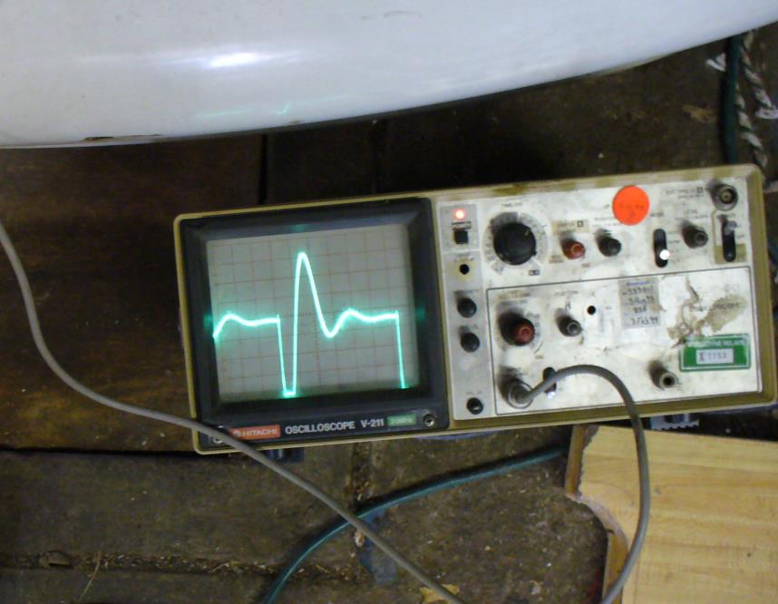
Princeton: This is a picture of extreme ringing of a 400 amp IGBT just before it blew up, because there were no capacitors in the circuit. The capacitors absorb the on-rush of current FROM the batteries when the MOSFETs shut off. The diodes ground out the inductive current from the motor. If you are using the controller as a light dimmer, you don't need the diodes.
I do agree with the use of some zeners or transient suppressors, in parallel with the power diodes, to suppress over-voltages. My controller periodically blows up MOSFETs for no obvious reason. The last time, I jumped in the car, stepped on the throttle, and popped 10 of my 12 FETs. I bought some 180v transient suppressors, that I plan to add.
Also my controller is water-cooled.
 |
|
|
|
|
10-19-2010, 06:26 PM
|
#3860 (permalink)
|
|
EcoModding Lurker
Join Date: Sep 2010
Location: usa
Posts: 50
Thanks: 15
Thanked 3 Times in 3 Posts
|
Would someone please show me a before and after picture of the drain voltages both with and without capacitors across B+ and gnd ?? Please explain how capacitors across the battery terminals suppress drain voltages. I'm confused.
|
|
|
|
|


