 10-20-2010, 06:10 PM
|
#3871 (permalink)
|
|
PaulH
Join Date: Feb 2008
Location: Maricopa, AZ (sort of. Actually outside of town)
Posts: 3,832
Thanks: 1,362
Thanked 1,202 Times in 765 Posts
|
Forget the capacitors for a second. Where does the future 1200 amps go that will be flowing through the mosfets, once they shut off? It's going to go through your resistor and diode. It WILL be the same current for a short period of time, because current can't change instantaneously. So, if you are suddenly forcing the current to go through a resistor and the freewheel diode, you are still stuck with Ohms law. V = I*R.
I = 1200amp (let's say).
Was the resistor like 20 Ohms or something? I forgot. Let's say 20 Ohms.
V = 1200*20 = 24000v. You should see 24000v drop from Drain to Battery + for an instant. So, the voltage that the mosfet will see from Drain to Source would be 24000v + Pack voltage. The mosfets are rated for 300v.
Am I missing something?
Let's see if we can come up with an analogy for this... Oprah, a very very large land mass, is moving at 100 mph. Suddenly, she is forced to go into a bog instead, since the path that her wheelchair is on is closed off. Then she starts singing the theme song to the Phantom of the Oprah... I hope that clears it up.
Actually, it's like a whole army of "people", marching in unison. The motor is like a human mass production plant. Putting out 1200 people per second. They need to be notified ahead of time to reduce production. Right now, while the mosfets are ON, the people have no problem just being shoved right out to their ultimate goal in life, B-. (In high school my ultimate goal was a D-, but we won't talked about that). So, now that the "doorway to heaven" (mosfet) is closed, the people have to still keep marching onward, but they have to go through the resistor and diode. The diode ain't nothin, but there are still 1200 people per minute being pumped out of the factory, now being squashed to death (increased pressure means higher voltage) trying to desperately make it across the terrible bog, which is filled with Malaria. They can't slow down either! There are people pushing on their backs, forcing them to move! This causes them to become very angry. Basically, a big fight breaks out, and they start breaking stuff, like the mosfets.
Last edited by MPaulHolmes; 10-20-2010 at 06:26 PM..
|
|
|

|
 Today Today
|
|
|
|
 Other popular topics in this forum...
|
|
|
|
 10-20-2010, 06:26 PM
|
#3872 (permalink)
|
|
EcoModding Lurker
Join Date: Sep 2010
Location: usa
Posts: 50
Thanks: 15
Thanked 3 Times in 3 Posts
|
Quote:
Originally Posted by MPaulHolmes

Forget the capacitors for a second. Where does the future 1200 amps go that will be flowing through the mosfets, once they shut off? It's going to go through your resistor and diode. It WILL be the same current for a short period of time, because current can't change instantaneously. So, if you are suddenly forcing the current to go through a resistor and the freewheel diode, you are still stuck with Ohms law. V = I*R.
I = 1200amp (let's say).
Was the resistor like 20 Ohms or something? I forgot. Let's say 20 Ohms.
V = 1200*20 = 2400v. You should see 2400v drop from Drain to Battery + for an instant. So, the voltage that the mosfet will see from Drain to Source would be 2400v + Pack voltage. The mosfets are rated for 300v.
Am I missing something?
Let's see if we can come up with an analogy for this... Oprah, a very very large land mass, is moving at 100 mph. Suddenly, she is forced to go into a bog instead, since the path that her wheelchair is on is closed off. Then she starts singing the theme song to the Phantom of the Oprah... I hope that clears it up.
|
What does this have to do with the capacitors? My assertion is that the capacitors are useful for adding longevity to the batteries but are almost useless at preventing inductive feedback.
In regards to the above analogy, I agree that a field is generated around the inductor (motor) which contains energy. This energy must be dissipated somehow, or face consequences of mosfet failure. We seem to disagree about the role of the capacitors in the protection of the mosfets. I do agree that the flyback diodes do offer some protection for the mosfets. Unfortunately, the flyback diodes drain the current from the inductor too quickly and this high current produces a magnetic field around the inductor of opposite polarity. Without a resistance to dissipate this energy, this produces an oscillation of voltages. We have created an inductor-capacitor oscillator. (The mosfet drain capacitance is the capacitor). |
|
|

|
 10-20-2010, 07:56 PM
|
#3873 (permalink)
|
|
PaulH
Join Date: Feb 2008
Location: Maricopa, AZ (sort of. Actually outside of town)
Posts: 3,832
Thanks: 1,362
Thanked 1,202 Times in 765 Posts
|
Let's address the capacitors:
You don't want big di/dt and inductance at the same time. That's because
V = L*di/dt.
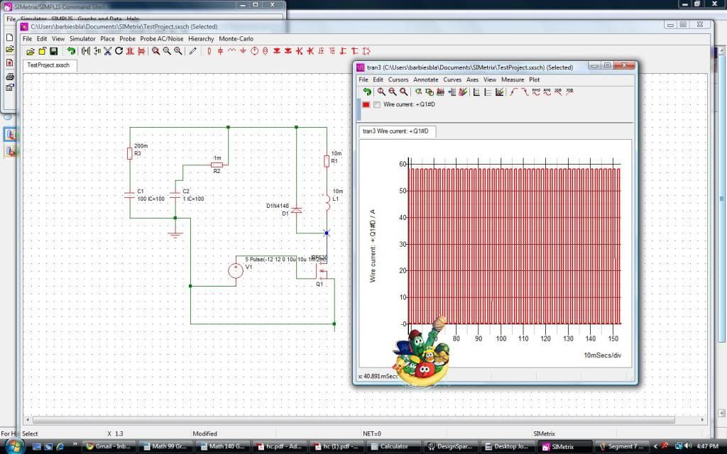
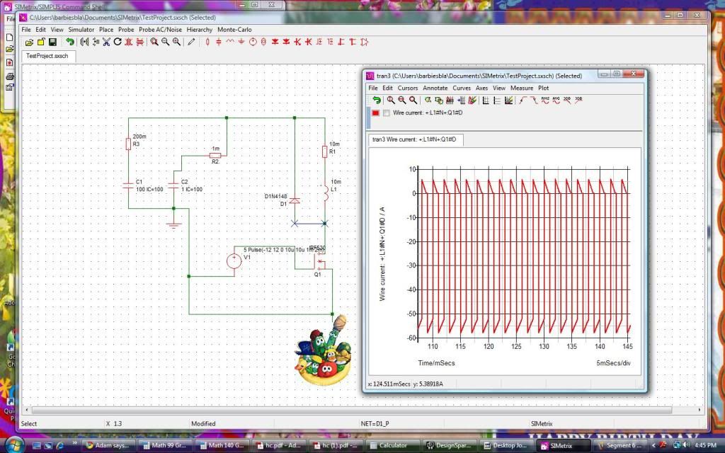
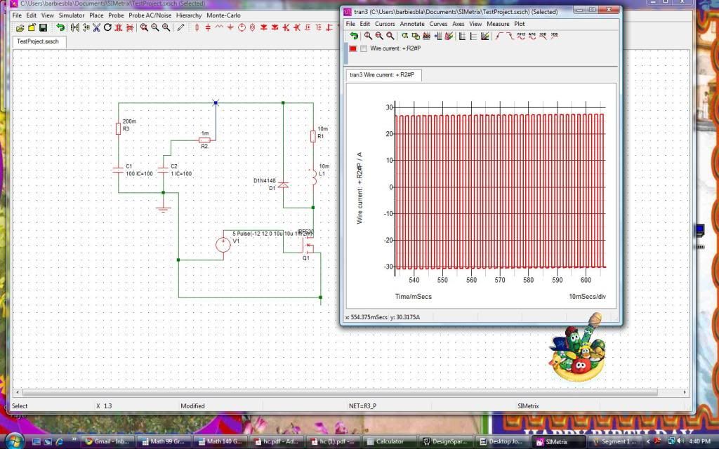
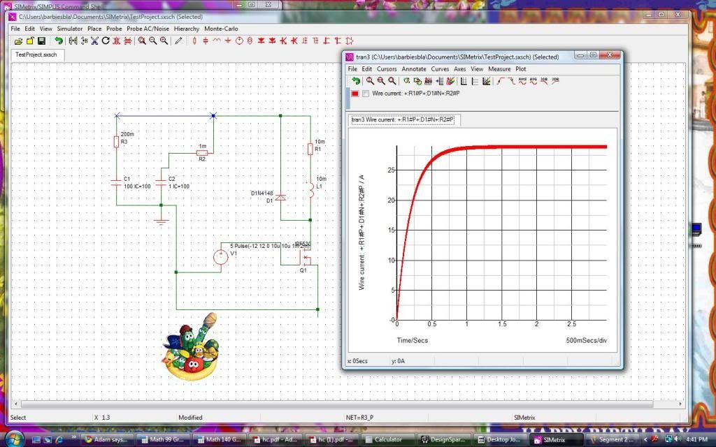
Now, I ran some simulations. Check out the pictures. Notice the pictures that have very large di/dt. Also notice the pictures that DON'T have large di/dt.
The equivalent series resistance of a battery string is pretty big. Maybe 100 or 200mOhm. The equivalent series resistance of a bunch of capacitors in parallel is going to be around 1mOhm to 10mOhm.
Look at the parts that have the blue highlighted part. That's what the current is in that part of the circuit.
This is the current right at the mosfet drain.
This is the current right at the diode anode.
This is the current that the capacitor bank sees. Big change in current. It's taking one for the team. It's lower resistance is making it so the batteries don't see the big change in current.
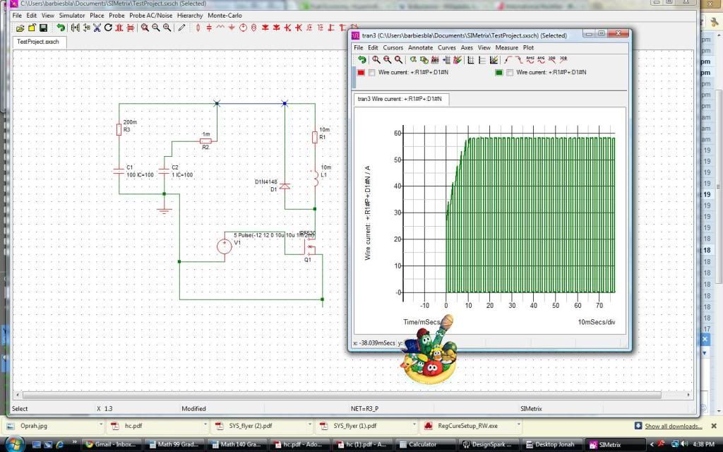
Next will be the small di/dt parts...
Last edited by MPaulHolmes; 10-20-2010 at 08:43 PM..
|
|
|

|
 10-20-2010, 07:57 PM
|
#3874 (permalink)
|
|
PaulH
Join Date: Feb 2008
Location: Maricopa, AZ (sort of. Actually outside of town)
Posts: 3,832
Thanks: 1,362
Thanked 1,202 Times in 765 Posts
|
small di/dt pictures
M- cable can be relatively long.
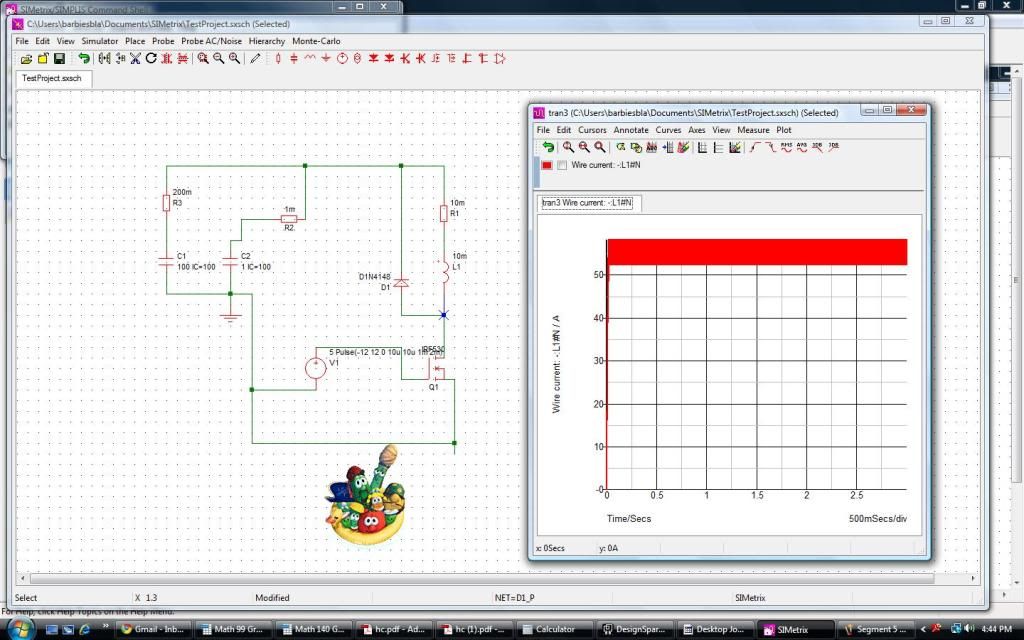
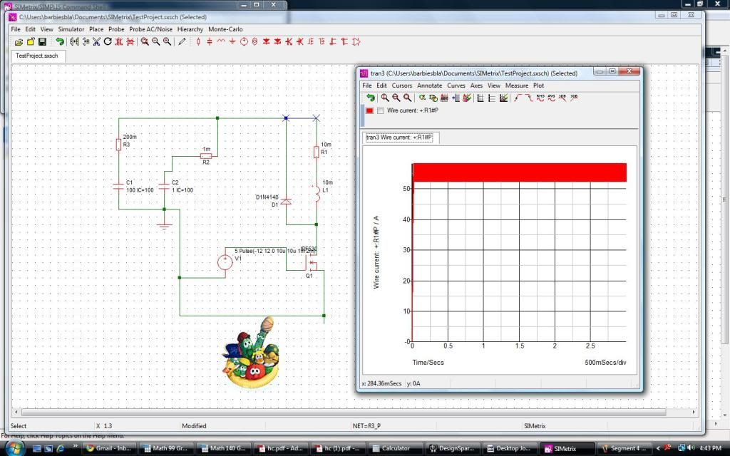
The batteries are seeing a very small di/dt (change in current), so L*di/dt is small.
Last edited by MPaulHolmes; 10-20-2010 at 08:47 PM..
|
|
|

|
 10-20-2010, 08:04 PM
|
#3875 (permalink)
|
|
EcoModding Lurker
Join Date: Sep 2010
Location: usa
Posts: 50
Thanks: 15
Thanked 3 Times in 3 Posts
|
I apologize for my ignorance. What was the point of the graphs again?
|
|
|

|
 10-20-2010, 08:07 PM
|
#3876 (permalink)
|
|
PaulH
Join Date: Feb 2008
Location: Maricopa, AZ (sort of. Actually outside of town)
Posts: 3,832
Thanks: 1,362
Thanked 1,202 Times in 765 Posts
|
Each blue segment that has a large current swing must be SHORT, because v = L*di/dt.
Each blue segment that has a small current swing can be long.
|
|
|

|
 10-20-2010, 08:12 PM
|
#3877 (permalink)
|
|
EcoModding Lurker
Join Date: Sep 2010
Location: usa
Posts: 50
Thanks: 15
Thanked 3 Times in 3 Posts
|
You might have to spell it out to me. Are you saying that the blue portions of the wires must be short to limit inductance of the wires?
|
|
|

|
 10-20-2010, 08:19 PM
|
#3878 (permalink)
|
|
PaulH
Join Date: Feb 2008
Location: Maricopa, AZ (sort of. Actually outside of town)
Posts: 3,832
Thanks: 1,362
Thanked 1,202 Times in 765 Posts
|
Exactly! And you only need to care about the wires that have the have the current swinging really high and low really really fast. The ones with a small change in current don't matter. v = (slope of current graph)*Inductance_in_wire. So, if the current isn't changing much, the wire inductance can be big, and the voltage spike from the changing current and the inductance will still be small.
But in those regions where the current is swinging from -50 to 0 or -20 to 30 or 0 to 50 amps, those have BIG CHANGE IN CURRENT IN A SHORT TIME, so the path must be short there.
|
|
|

|
|
The Following User Says Thank You to MPaulHolmes For This Useful Post:
|
|
 10-20-2010, 08:23 PM
|
#3879 (permalink)
|
|
EcoModding Lurker
Join Date: Sep 2010
Location: usa
Posts: 50
Thanks: 15
Thanked 3 Times in 3 Posts
|
And what does this have to do with our circuits?
|
|
|

|
 10-20-2010, 08:32 PM
|
#3880 (permalink)
|
|
PaulH
Join Date: Feb 2008
Location: Maricopa, AZ (sort of. Actually outside of town)
Posts: 3,832
Thanks: 1,362
Thanked 1,202 Times in 765 Posts
|
This is our circuit. The first LARGE capacitor is what I was using to simulate the battery. 100 Farads will act like a battery for a few seconds (which is all the simulation is for). The 2nd capacitor in parallel is the "capacitor bank". The diode is the freewheel diode. The mosfet at the bottom is the mosfet. The inductor and the series resistor (0.01 Ohm) is the motor. The voltage source at the bottom is the pwm for the mosfet.
|
|
|

|
|