 10-31-2012, 07:39 PM
|
#5901 (permalink)
|
|
EcoModding Lurker
Join Date: Nov 2009
Location: Akron, OH
Posts: 5
Thanks: 0
Thanked 1 Time in 1 Post
|
Hi Paul
Am I putting these ideas in the correct place?
Other improvements are 1. IC sockets for removal to reprogram or isolate all inputs. You can probe each pin for correct inputs. 2. Build power fets on a heat disapator with fan. There is no such thing as to cold. 3. Put LEDs at each important location. Power, Pot. Pulse ect. in a readable labelled location.
I have found other circuit diagrams but do not know how to post.
Why are these car adds and repeating junk post all over?
|
|
|

|
 Today Today
|
|
|
|
 Other popular topics in this forum...
|
|
|
|
|
11-01-2012, 01:26 PM
|
#5902 (permalink)
|
|
PaulH
Join Date: Feb 2008
Location: Maricopa, AZ (sort of. Actually outside of town)
Posts: 3,832
Thanks: 1,362
Thanked 1,202 Times in 765 Posts
|
Hi James, sure you could post stuff here. I have used IC sockets before, but some people had trouble with bad connections after close to a year. I think maybe corrosion was an issue. Mounting the mosfets' backs directly to metal would improve their ability to remove heat, but it makes the heat spreader a part of the circuit. Also, there can be issues with the heat spreader switching from high to low voltage really fast. But it's definitely worth pursuing. LEDs are a good idea. That could show that everything is working as it should, but it would also increase the current usage by another 100mA or something. I think the ads are so the site can make a little money. It's a lot of work to keep it running.
Hi Joe! I'm going to check with scope probes removed when I get home. For a given M- current, the spike actually decreased as voltage went up (well, at 36v the spike was less). Maybe that's because the mosfet was actually passing less current, even though M- current was the same as at 24v? I'm going to run the voltage up to 150 or 160 and test it at lower currents and see how things look. I don't have enough resistance wire for high voltage high amp tests. If I cranked it up to 150v with the currrent setup, it would be 1000 amps at 100% duty, which is great, but I'm testing 2 mosfets and 2 diodes. haha. I'd be blasted to another dimension. Maybe I could have throttle range from 0 - 10%? Sounds scary, but I might do that.
Hmm... What's the affect of, say, 100kw of power being dissipated into a bunch of water? Dang! 1000 liter of water that starts at 20 degC and ends at 90 degC can take 81.7kW for a full hour! then you can take a nice warm bath, and also cook some oatmeal with the water once the testing is done.
Last edited by MPaulHolmes; 11-01-2012 at 01:34 PM..
|
|
|
|
|
11-01-2012, 08:02 PM
|
#5903 (permalink)
|
|
PaulH
Join Date: Feb 2008
Location: Maricopa, AZ (sort of. Actually outside of town)
Posts: 3,832
Thanks: 1,362
Thanked 1,202 Times in 765 Posts
|
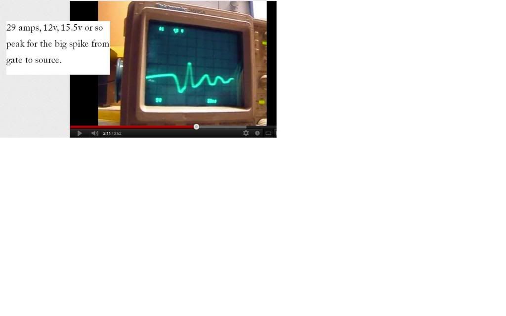
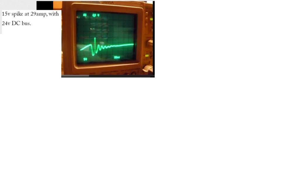
I get it up to 152 amps this time with the resistor coil in a water bath. Still at 24v, but with the oscilloscope disconnected. TVS temperature climbs pretty fast at 152 amps! But it could just be the mosfet legs getting hot, and that heat transferring to the TVS?
Here's 12v DC bus, at 29 amps, from gate to source:
Here's 24v DC bus, at 29 amps, from gate to source:
Last edited by MPaulHolmes; 11-03-2012 at 03:14 AM..
|
|
|
|
|
11-04-2012, 01:28 AM
|
#5904 (permalink)
|
|
PaulH
Join Date: Feb 2008
Location: Maricopa, AZ (sort of. Actually outside of town)
Posts: 3,832
Thanks: 1,362
Thanked 1,202 Times in 765 Posts
|
I should compare apples to apples. I should have been comparing the same BATTERY amps for different bus voltages, since the battery amps are the same as the current going through the mosfets.
|
|
|
|
|
11-07-2012, 05:56 PM
|
#5905 (permalink)
|
|
EcoModding Lurker
Join Date: Aug 2012
Location: Germany, Saarland
Posts: 8
Thanks: 1
Thanked 0 Times in 0 Posts
|
I'm back but still with bad news... So i got my new hass 300-s sensor. We changed the wiring and connected it to the board but now still when i turn it on the yellow led is on and when i "accelerate" the led starts flashing. Has it to do that i havent connected it yet to the power board and no motor is connected? I really dont know...
|
|
|
|
|
11-07-2012, 06:02 PM
|
#5906 (permalink)
|
|
PaulH
Join Date: Feb 2008
Location: Maricopa, AZ (sort of. Actually outside of town)
Posts: 3,832
Thanks: 1,362
Thanked 1,202 Times in 765 Posts
|
It sounds like it's working. It flags an error if the pwm goes to 100% and the current feedback is zero. It's to avoid problems people had in the past with contactors that would open each time the throttle is released. In the case of one poor guy, he stepped on the throttle slowly, which was enough for nonzero throttle to the controller, but not enough to close the contactor. PWM ramped up to 100% trying to get nonzero current feedback, and then the contactor closed with the PWM at 100%, a DEAD SHORT, and the controller got blasted into outer space. This software fix seemed to take care of the problem. At least I haven't heard anything like it since.
|
|
|
|
|
11-07-2012, 06:04 PM
|
#5907 (permalink)
|
|
EcoModding Lurker
Join Date: Aug 2012
Location: Germany, Saarland
Posts: 8
Thanks: 1
Thanked 0 Times in 0 Posts
|
So i see it right that the yellow and green led has to be on? or isnt it just the green one?
|
|
|
|
|
11-07-2012, 06:18 PM
|
#5908 (permalink)
|
|
PaulH
Join Date: Feb 2008
Location: Maricopa, AZ (sort of. Actually outside of town)
Posts: 3,832
Thanks: 1,362
Thanked 1,202 Times in 765 Posts
|
At zero throttle, both LEDs should be on, and not blinking.
|
|
|
|
|
11-11-2012, 12:25 AM
|
#5909 (permalink)
|
|
EcoModding Lurker
Join Date: Nov 2009
Location: Akron, OH
Posts: 5
Thanks: 0
Thanked 1 Time in 1 Post
|
Quote:
Originally Posted by jamesweirick5

I have a BS in Electronic Technology with equipment and get the theary and concepts. I do not have your valuable experience. Your huge threads are difficult to process easily. I have converted 8 cars cheaply and my 20A chargers cost about $10 by using just a full wave bridge.
Your 500A to 800A controller is to complex to troubleshoot readily. If I had measurements (V) of the micro processor inputs and outputs under success and different failures, then I could troubleshoot the simple circuits left.
I have built a 1000A controller using your power driver and fets with diodes. I have bought a cheap PWM control to drive it. I will use smaller wire resistance to current limit at first. I still have to find a simple current limit cricuit to connect to the driver chip. I have upgraded your fets and diodes and mounted them on big heat fins with a fan for supperior cooling. This contoller costs under $200 in parts. I do understand the dire need for your additional complexities and computer. I know I will be blowing some stuff up but hope that you can reduce the failures.
Jim
|
Does anyone have any simple pwm controller designs to copy. I need current limit and maybe ramp up speed. The 555 timers start at 10% and go to 90%. I think I need 0% - 100%. I want to start with a basic solid simple tested design. |
|
|
|
|
11-11-2012, 12:31 AM
|
#5910 (permalink)
|
|
EcoModding Lurker
Join Date: Nov 2009
Location: Akron, OH
Posts: 5
Thanks: 0
Thanked 1 Time in 1 Post
|
Are there any other DIY controller resources other than DIY & Paul's & EValbum
|
|
|
|
|


