 08-11-2009, 03:53 PM
|
#51 (permalink)
|
|
ReVolt Enthusiast
Join Date: Jun 2009
Location: Michigan, USA
Posts: 239
Thanks: 97
Thanked 47 Times in 40 Posts
|
Dual Parallel Power Diodes ???
Hi Adam,
I know that you have changed the power diodes from 60A (Dual 30A) to 90A diodes on your Power PCB to increase the current capacity.
Did you ever look at using (2) STTH6002 in parallel for a 120A operation ? I know the MOSFET’s are rated at 120A and that would seam to be logical for the MOSFETs and Power Diodes to have the same 120A maximum current rating.
I have not tried to see if the Power PCB layout would allow for this. The Sandwich Power PCB layout you have used, might let you put the power diodes back2back ??? for a good fit ???

-Mark
Last edited by sawickm; 08-11-2009 at 04:18 PM..
|
|
|

|
 Today Today
|
|
|
|
 Other popular topics in this forum...
|
|
|
|
 08-11-2009, 04:01 PM
|
#52 (permalink)
|
|
Master EcoModder
Join Date: Apr 2009
Location: Charlton MA, USA
Posts: 463
Thanks: 31
Thanked 183 Times in 94 Posts
|
Hi Mark,
I have not thought about using 2 diodes to get the amount of power needed. It will be a challenge to find space for these extra diodes. I will look into this and let you know.
-Adam
|
|
|

|
 08-11-2009, 08:10 PM
|
#53 (permalink)
|
|
EcoModder Student
Join Date: Nov 2008
Location: Youngsville, NC
Posts: 117
Thanks: 11
Thanked 14 Times in 13 Posts
|
Quote:
Originally Posted by adamj12b

I have been working over the past few weeks on getting ready to do high voltage testing on a small version of the controller. I have charged up 20 SLA 12V batteries and acquired a 130VDC 26A 2.65 HP treadmill motor and machined the small controller. I am going to start with 9 batteries and measure the voltage spikes and keep adding batteries till A: I reach 14 or 15 batteries, or B: I break the controller and call it as 1 less then what broke it.
|
Adam,
Now this is probably the most important bit of news in this whole thread. This is really exciting and I can't wait to see what you find out. I have wondered about the real voltage limits of this design. Paul mentioned 144 volts for sure, maybe 156. Now you are going to show us the real limit. 
Good luck with this testing. I'm sure I don't have to remind you to post results. Take your time and get as much data as possible.
And thanks again for the pretty pictures.
Eric
__________________
1995 BMW 318i EV in the making
|
|
|

|
 08-11-2009, 11:15 PM
|
#54 (permalink)
|
|
PaulH
Join Date: Feb 2008
Location: Maricopa, AZ (sort of. Actually outside of town)
Posts: 3,832
Thanks: 1,362
Thanked 1,202 Times in 765 Posts
|
Oh crap, that reminds me that I'm supposed to mail Adam the mosfets/diodes for his rather cruel high voltage testing! oops! I forgot today! I'm an idiot!
|
|
|

|
|
The Following User Says Thank You to MPaulHolmes For This Useful Post:
|
|
 08-31-2009, 01:56 PM
|
#55 (permalink)
|
|
EcoModding Lurker
Join Date: Jul 2009
Location: Sweden
Posts: 10
Thanks: 1
Thanked 0 Times in 0 Posts
|
Quote:
Originally Posted by adamj12b

The controller will have the option of being water cooled if I need it. If it can stay cool by just the air moving over it, I will not using the water cooling, Saving weight.
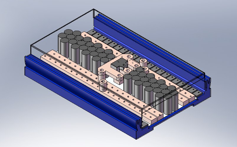
No Water Blocks:

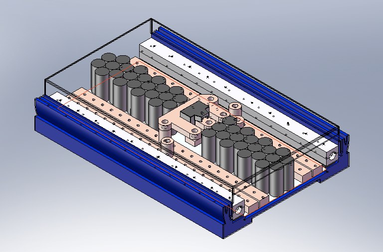
With Water Blocks:

-Adam |
Just a thought: what's the thermal resistance from junction to topside of case?
If resistance is high then water cooling of the topside will probably not make a big difference.
|
|
|

|
 09-01-2009, 08:25 AM
|
#56 (permalink)
|
|
Master EcoModder
Join Date: Apr 2009
Location: Charlton MA, USA
Posts: 463
Thanks: 31
Thanked 183 Times in 94 Posts
|
Hi Bjn,
I have not thought about that before. I am working on another design and found out that the heat sink has to contact the back, metal side of the mosfets and diodes. They are designed for 90% of the heat to be transferred through the back.
I will probably just bend the mosfets up so that they are vertical and attach them to the side of the water block. This will work well, but the water will have to run continuously because there is no additional cooling.
-Adam
|
|
|

|
 09-24-2009, 09:29 AM
|
#57 (permalink)
|
|
Master EcoModder
Join Date: Apr 2009
Location: Charlton MA, USA
Posts: 463
Thanks: 31
Thanked 183 Times in 94 Posts
|
Hey Guys,
Just another update. I know its been awhile, but I have been busy trying to get my house ready to move in.
We have begun removing the body from the frame of the car so that we can sand bast and paint it. We have also recieved our manual steering rack that we will be putting in the car. This will eliminate all of the power steering pump and hardware. It should drop a few pounds from the car. Once the frame is clean and painted, it will be put back under the body so that the body work can begin. First will be chemical stripper to remove the paint. This will take a few coats, as there is 3 or 4 different colors on the car now. Then we will begin the fiberglass repair work from when the new nose and rear quarter were put on wrong by a previous owner. After that, its time to play musical cars to make room in the small garage that is used as a painting booth.
We have also decided to go with Thunder Sky cells instead of the sky energy. This will still be 45 cells, not sure still weather it will be the 180Ah cells or something smaller, The 180 cells are what seems to be a very optimal cell for the goals of the car. They would provide a good run time, as well as huge amounts of power for showing off.
Well here are some pictures of removing the body and the new manual steering rack.


Enjoy
-Adam |
|
|

|
 09-24-2009, 09:32 AM
|
#58 (permalink)
|
|
Master EcoModder
Join Date: Apr 2009
Location: Charlton MA, USA
Posts: 463
Thanks: 31
Thanked 183 Times in 94 Posts
|
Also,
We finished getting the body off of the car tuesday night. We then rolled the chassis out into the driveway and finished removing the 3 gas lines that were hard to get to, and the rest of the steering linkage and steering box that was left.
We did a little bit of pressure washing to remove some of the grease and grime as to not get so dirty when working on it.
When we rolled it back in to the garage, we started mocking up the new manual rack. After looking over the C4, and trying a few things, we decided that we need to mount the rack so that the tie rod ends are on the top of the knuckles. This will require re-tapering the holes for the tie rod ends. We took a bunch of pictures and some measurements.
I have since drawn up a mount in CAD. The mount is made out of 3/16" thick 1.25" square tube steel. This will be welded to the frame. The rack will attach to the tube steel with some clamp mounts I designed as well. I will be CNC machining these out of 1.875" thick aluminum blocks. These are 2 pieces that will have 2 bolts to clamp each end of the rack to the frame. I believe this should hold up very well.
Heres a picture of the mount and some from the mock up:


-Adam |
|
|

|
 09-29-2009, 08:50 AM
|
#59 (permalink)
|
|
Master EcoModder
Join Date: Nov 2008
Location: Massachusetts, USA
Posts: 442
Thanks: 1
Thanked 60 Times in 45 Posts
|
Any more updates on the controller setup?
45 180Ah Thundersky cells would be awesome for the vette as long of the cabling can handle the current when showing off.  |
|
|

|
 09-29-2009, 09:14 AM
|
#60 (permalink)
|
|
Master EcoModder
Join Date: Apr 2009
Location: Charlton MA, USA
Posts: 463
Thanks: 31
Thanked 183 Times in 94 Posts
|
The controller is still in the golf cart. Its holding up real well so far, but I have to figure out why the bus bars are turning blue in places. I have no idea....
Im hoping that the 180's will happen. We have to come up with the additional $4k to pay for the extra capacity, so we have been selling everything we don't want or need or find in storage, on ebay.  Hopefully somebody will buy some of the high dollar stuff soon so we can buy the motor.
As for the cabling, I have been talking to my rep for the supply house that we use for work. He is able to get me 4/0 welding cable for $3.35 a foot. Since I don't need it to connect the batteries together, I figure I only need at most 45 feet, thats $150. The spec sheet says that in a 600V in-line system it can handle 310 Amps continuous, and in a 100 foot loop welding circuit it can handle 600 Amps at a 60% duty cycle. It should be able to take very large amounts of current for burnouts and drag racing. 
Here's the spec sheet: http://www.generalcable.com/NR/rdonl...gSpecSheet.pdf
-Adam
|
|
|

|
|