Go Back   EcoModder Forum > EcoModding > Fossil Fuel Free
Register Now
 Register Now
 

Reply  Post New Thread
 
Submit Tools LinkBack Thread Tools
Old 08-06-2009, 12:22 AM   #41 (permalink)
Needz Moar Jiggawatts
 
mcmahon.craig's Avatar
 
Join Date: Sep 2008
Location: Canada
Posts: 30
Thanks: 5
Thanked 3 Times in 3 Posts
I LOVE the Super OSMC idea. I was thinking of doing that at some point (when I have money) but I'm glad someone is doing it now.

__________________
In theory, theory and practice are the same. In practice, they aren't.
  Reply With Quote
Alt Today
Popular topics

Other popular topics in this forum...

   
Old 08-06-2009, 02:14 AM   #42 (permalink)
EcoModder Student
 
esoneson's Avatar
 
Join Date: Nov 2008
Location: Youngsville, NC
Posts: 117
Thanks: 11
Thanked 14 Times in 13 Posts
Quote:
Originally Posted by MPaulHolmes View Post
Eric, you are right that there should be a separate driver board. I want to make that change too. .
Paul,

This is really good. It gives a lot of flexibility for power selection from the bike size controller to the 3200 pound dream machine controller I have in mind. We should plan on adding this feature on the next round of test controllers. I, for one, would be very interested.

Let's not lose sight of this feature.

Many thanks for listening.

Eric
__________________
1995 BMW 318i EV in the making
  Reply With Quote
Old 08-11-2009, 12:00 PM   #43 (permalink)
ReVolt Enthusiast
 
Join Date: Jun 2009
Location: Michigan, USA
Posts: 239
Thanks: 97
Thanked 47 Times in 40 Posts
Excellent Job !!!

Hi Adam,

I want to thank you for sharing that information on your High Performance Motor Controller.

Like Eric, I too am interested in a performance version of Paul’s Revolt Motor Controller. I would be very interested in purchasing a Kit, or just the set of PCB's for your High Performance Motor Controller !!! The supplier for the heat sinked case is not a problem, a new case could easily be designed around you set of PCB’s.

Also are you using the same Hall Sensor in Paul’s Cougar Controller (LEM HASS 300-S) ??? Will it work with the higher current output of your High Performance Motor Controller ?

Thanks again,

Mark

Last edited by sawickm; 08-11-2009 at 12:20 PM..
  Reply With Quote
Old 08-11-2009, 01:29 PM   #44 (permalink)
Master EcoModder
 
Join Date: Apr 2009
Location: Charlton MA, USA
Posts: 463

EVVette - '71 Chevy Corvette Coupe
Thanks: 31
Thanked 183 Times in 94 Posts
Hi Guys,

Thanks for all the compliments. They are what keep me working.

First off, I am using the same current sensor. I created a piece that I am calling the current bridge as it rises over the other parts of the controller. It is made out of copper and forks out into 3 bars. It is then rejoined at the other end back into 1 bar. Paul and I have discussed this and believe that simply what it will do is divide the current by 3, allowing the small sensor to read large current. then in the programming, it will just multiply by 3 to read the proper current. I will be calibrating it also with a current meter, so it might be multiplied by something slightly different then 3.

As for kits, I am hoping to sell some. I love this kind of stuff, but money is not always around to do research. So if i could make a little bit to build bigger and better controllers that would be awesome!

On to something you guys might really like. I have been working over the past few weeks on getting ready to do high voltage testing on a small version of the controller. I have charged up 20 SLA 12V batteries and acquired a 130VDC 26A 2.65 HP treadmill motor and machined the small controller. I am going to start with 9 batteries and measure the voltage spikes and keep adding batteries till A: I reach 14 or 15 batteries, or B: I break the controller and call it as 1 less then what broke it.

Some pictures of the test controller:


Mosfets and Diodes are on the bottom side clamped to the heat-sink through the PCB:


Test Control Board:
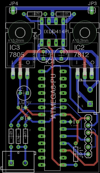

While I was designing the 2 pair test controller, I came across a very very good layout for the controller. I decided to see where I could take this design. I ended up with a recreation of Paul's controller on a more friendly layout. He seemed to really like the layout. It contained 10 pairs just like his, but only had 15 caps. Since he decided to go with the 820uf caps now this is not a problem being 1 down. It also has places to mount 2 of the poly spike suppression caps. And its just beautiful!!


The controller uses a slimed down version of the fet driver board that I designed for my controller. This one is 5 fets per driver down from 7.


This controller is set up like the test stand where the PCB is the top clamp for holding the mosfets and diodes to the heat-sink. The heatsink I plan on using is from HeatsinkUSA.com. It is the small size they offer. It should be a perfect size for the controller. The PCB is 12" long and 5.3" wide and the heat-sink is 12" long and 5.375" wide. With a small aluminum box around the bottom of the heat-sink it would be perfect. The heat-sink will have a channel milled down the middle to allow room for the M- buss bar. The 3 buss bars will be 1/4" thick by 3/4" wide. Should be heavy enough for a continuous 600A. I will also drill and tap all 20 holes for the mosfets and diodes. The heat-sink could be made to only the length of the mosfet/diode section with just regular sheet metal over the rest, or it could just be the entire length of the controller. What do you guys think?

Now for the bad news....I dont have money to build this controller. It might be awhile before you will see one, but I plan on building one for my golf cart. I have the PCB, just need to mill it, but it ends there for materials.

I hope to start enlarging it, Im thinking 15 pairs and 24 caps. it will make the controller about 7-8" longer for a total of about 18" and 5.5" wide. Long and Skinny.


Please let me know what you guys think.

-Adam
__________________
www.EVVette.com - 1971 Corvette Coupe Conversion to all Electric!
www.AdamBrunette.com - Machining, CNC, Robotics and Electronics.

You can download RTD Explorer for the Cougar controllers at www.EVVette.com
  Reply With Quote
Old 08-11-2009, 01:54 PM   #45 (permalink)
Dartmouth 2010
 
SVOboy's Avatar
 
Join Date: Nov 2007
Location: Hanover, NH
Posts: 6,447

Vegan Powa! - '91 Honda CRX DX
Team Honda
90 day: 66.52 mpg (US)
Thanks: 92
Thanked 123 Times in 90 Posts
Send a message via AIM to SVOboy Send a message via MSN to SVOboy Send a message via Yahoo to SVOboy
Looks like sharp work, keep it up!
  Reply With Quote
Old 08-11-2009, 02:13 PM   #46 (permalink)
ReVolt Enthusiast
 
Join Date: Jun 2009
Location: Michigan, USA
Posts: 239
Thanks: 97
Thanked 47 Times in 40 Posts
Amazing Work !!!

Hi Adam,

The work you have done is simply amazing !!!

I love how flexible the whole concept for Open Revolt controller is. The configurations for the Open Revolt design large or small are only limited to your imagination. Your new power PCB and mini controller PCB really looks great !!!

I am also impressed with your attention to detail on your PCB layouts. The matched trace lengths on the Mosfet driver PCB to control the gate resistor timing show that.

Keep up the good work !!!

Mark
  Reply With Quote
Old 08-11-2009, 02:58 PM   #47 (permalink)
ReVolt Enthusiast
 
Join Date: Jun 2009
Location: Michigan, USA
Posts: 239
Thanks: 97
Thanked 47 Times in 40 Posts
Sandwich Layout

Hi Adam,

I also wanted to comment on you placing the Mosfets and Diodes are on the bottom side clamped to the heat-sink through the PCB.

I like the idea of a Sandwich Power PCB Layout, heatsink on top, PCB in the middle with the Mosfet’s facing up and the capacitors and electronics facing down, and buss bars on the bottom. I also envisioned the Mosfets mounted to an aluminum plate that would allow a modular heatsink or water jacket to be bolted to it on the opposite side.

Another idea I had was to make 100 Amp power modules that could be modularly configured, 500A, 1000A, 1500A, etc… The layout would use (1) IRFP4668 and (2) STTH6002, and (2) 820uf caps. The configuration would allow for 100A – 120A operation.

Regards,

Mark

Last edited by sawickm; 08-11-2009 at 03:10 PM..
  Reply With Quote
Old 08-11-2009, 03:30 PM   #48 (permalink)
Master EcoModder
 
Join Date: Apr 2009
Location: Charlton MA, USA
Posts: 463

EVVette - '71 Chevy Corvette Coupe
Thanks: 31
Thanked 183 Times in 94 Posts
Hi Mark,

I have had an idea of the controller built in this modular design. It would all be held together by the buss bars and the heat-sink. The only interesting thing would be supplying the pwm to the mosfet drivers. On my controller I redesigned the control board to have 3 molex outputs that small identical length pigtails could connect the 3 driver boards. With a modular board there will be a limit, Most likely the number of modules. An idea I just had about this could be a small daughter board that would breakout the single pwm into X, one for each driver board.

-Adam
__________________
www.EVVette.com - 1971 Corvette Coupe Conversion to all Electric!
www.AdamBrunette.com - Machining, CNC, Robotics and Electronics.

You can download RTD Explorer for the Cougar controllers at www.EVVette.com
  Reply With Quote
Old 08-11-2009, 04:17 PM   #49 (permalink)
ReVolt Enthusiast
 
Join Date: Jun 2009
Location: Michigan, USA
Posts: 239
Thanks: 97
Thanked 47 Times in 40 Posts
Modular FET Driver daughter board

Hi Adam,

Are you talking about having a FET Driver daughter board that would have the all the MIC4451 circuitry for a single 100A module ? and a common input (Molex connector) from the HCPL-4504 for how ever many modules used ?

You could still use your existing 5x or 7x FET Diver PCB’s. Instead of single 100A-120A module, design a (5x) Power PCB (500–600A) that your 5x FET Diver PCB could connect to. You could then use multiple (5x) Power PCB's to expand from 500-600A to: 1000-1200A, 1500-1800A, 2000-2400A, etc…. ??? and make the Molex connector on the controller handle the additional Driver PCB modules.

At what frequency does the PWM operate ? do you use wire or coax for connecting the controller PCB to the FET driver PCB's ???

?????

Mark
  Reply With Quote
Old 08-11-2009, 04:28 PM   #50 (permalink)
Master EcoModder
 
Join Date: Apr 2009
Location: Charlton MA, USA
Posts: 463

EVVette - '71 Chevy Corvette Coupe
Thanks: 31
Thanked 183 Times in 94 Posts
Hi Mark,

I see what you mean now, I read your other post wrong. I would do what you suggest and add in 500A sections. I might do a 3 fet design to be able to add in 200-300A sections. The only problem might be heat-sink and even more buss bars. I have an idea about how to expand the heat-sinks, and even the B+ and B- buss bars, but I cannot think of how the M- bar could be expanded without getting in the way of the heat-sink. I think that it would need to be replaced with one designed for X number of power module's. It would also leave a problem of the cover. I think I could draw up something that could have flanges on it and it would screw together to create a box. It would have to have end ones still, but i guess that would be in the basic controller.

-Adam

__________________
www.EVVette.com - 1971 Corvette Coupe Conversion to all Electric!
www.AdamBrunette.com - Machining, CNC, Robotics and Electronics.

You can download RTD Explorer for the Cougar controllers at www.EVVette.com
  Reply With Quote
Reply  Post New Thread


Similar Threads
Thread Thread Starter Forum Replies Last Post
Electric car conversion: Project ForkenSwift MetroMPG Fossil Fuel Free 1056 12-14-2024 01:21 AM
1995 Toyota pickup EV conversion... ModelE EcoModding Central 13 01-06-2010 12:08 AM
Ford Explorer EV Conversion in MA Matt Herring Fossil Fuel Free 0 05-19-2009 01:10 PM
Riley's EV conversion WannabeEVer Fossil Fuel Free 3 06-28-2008 01:47 PM
Practical? Possible? Taurus EV Conversion WaxyChicken Fossil Fuel Free 30 01-18-2008 12:12 AM


Powered by vBulletin® Version 3.8.11
Copyright ©2000 - 2024, vBulletin Solutions Inc.
Content Relevant URLs by vBSEO 3.5.2
All content copyright EcoModder.com