 09-06-2012, 10:13 PM
|
#371 (permalink)
|
|
Master EcoModder
Join Date: May 2012
Location: Tampa, FL
Posts: 1,745
Thanks: 206
Thanked 420 Times in 302 Posts
|
thank you! i have PSE 10, free from school, but never learned how to use it.
__________________


|
|
|

|
 Today Today
|
|
|
|
 Other popular topics in this forum...
|
|
|
|
 10-13-2012, 04:10 PM
|
#372 (permalink)
|
|
Master EcoModder
Join Date: Jan 2008
Location: Sanger,Texas,U.S.A.
Posts: 16,496
Thanks: 24,517
Thanked 7,436 Times in 4,817 Posts
|
Bonneville and the 'Template'
I was going to kick some numbers around from the Bonneville trip as related to the 'Template'.
*From the 'travel' portion of the 4200 + mile trip I was indicating 34 mpg at 70 mph.
*This would be a 45.92% improvement from the truck's baseline of 23.3 mpg at the same velocity.
*From GM's SAE Paper relating HWY mpg to drag coefficient,the 45.92% mpg increase would require that the Cd fall 76.53%,from 0.44 to 0.103.
*If I used a high-elevation air density value for the entire distance based on Rick Gold's density altitude for Bonneville of 5,600-feet,and 0.0019309 slugs vs 0.00238 (standard) then the Cd degrades to Cd 0.1268.
*With the new,lower, frontal area based on the photo-enlargement of Toyota's T-100 front elevation view,the Cd degrades to 0.1349.
*I'm not entirely comfortable with the number,so just for talkin' purposes,maybe we'd say it's in Cd 0.16 territory.
*I have brought the nose up to the 1968 R.G.S.White' minimums for low drag,but otherwise,the significant modifications have been in the aft-body as per Hucho's recommendations for body elongation.
*It appears to work.
* If I finish the 18-inch 'stinger' and install it,along with restoring the other missing components,it seems like it's not much of a stretch to the imagination that the truck will come right down to a Cd on the order of 0.13.
*Next stop is the A2 Wind Tunnel LLC facility in North Carolina.With their load cells,I should be able to finally nail down the actual Cd.
*Until then,I'd say that the "Template" can be used with a pretty high degree of confidence for drag reduction.
*And we can thank the likes of Jaray,Fachsenfeld,Kamm,Elliott,Heald,Lay,Breer,and so many others who did all the heavy lifting for us so long ago,such that we can have such simple tools to work with today.
*Another thing is that much of the elongation can be done with inflatable structures which won't impact urban driving 'practicality.'
*For those of you who will be trick- or -treating this season,you can be thinking about some of the inflatable yard decorations you'll be seeing.Christmas also!
__________________
Photobucket album: http://s1271.photobucket.com/albums/jj622/aerohead2/
|
|
|

|
|
The Following 2 Users Say Thank You to aerohead For This Useful Post:
|
|
 10-27-2012, 03:10 PM
|
#373 (permalink)
|
|
Master EcoModder
Join Date: Jan 2008
Location: Sanger,Texas,U.S.A.
Posts: 16,496
Thanks: 24,517
Thanked 7,436 Times in 4,817 Posts
|
New Images
I have done a few additional pictorial representations which I wanted to add just to muddy the waters further.
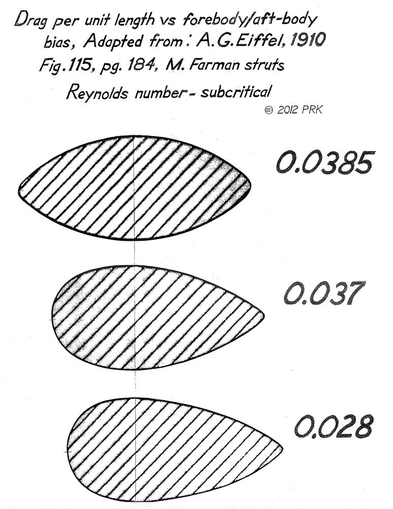
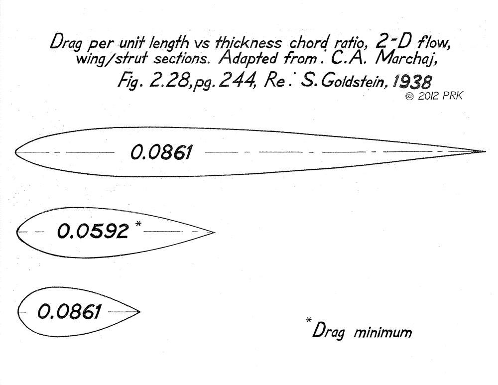
The first two are for 2-dimensional flow sections and struts which illustrate the significance of the aft body to low drag and then,the significance of the thickness ratio to drag.In streamlining,there is always a 'sweet-spot',where both pressure drag and skin-friction are both at their minimums.  
--------------------------------------------------------------------------
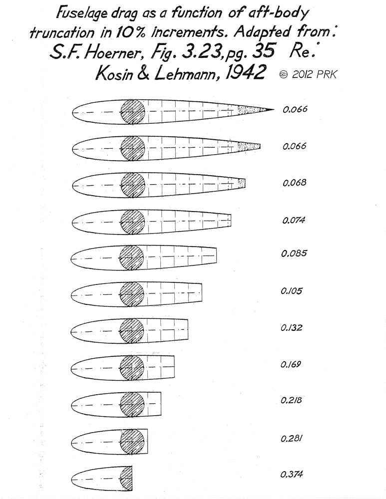
The 3rd image is a pictorial representation of Lehmann and Kosin's fuselage
drag table posted earlier in the 'Template' threads.
You can easier see how the aft-body of the fuselage reduces the Cd by 5.66X.Of course,in an automobile the overall drag will include the cooling system,wheels,interference drag,etc.,however you can clearly see why the aft-body is so significant to low drag. 
-------------------------------------------------------------------------
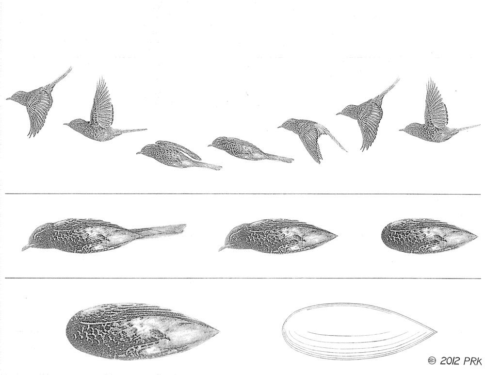
The 4th image is "Sparrowdynamics",or a look at 'Bounding' flight which is technique used by small birds flying into a headwind,whereas the wingbeat is suspended momentarily,with wings completely folded,and the bird's body taking on the form of a streamline body of revolution if you will,which if a smooth,rigid surface would have a drag coefficient of Cd 0.04 sans tail feathers,legs,beak,head,and wings.
You can see how Pierre Julienne or Santos-Dumont might have been inspired by bird flight ,as was the Lillianthal Brothers,when designing their airships.

The image is adapted from an illustration by Ad Cameron for Reader's Digest Edition,'BIRDS' Their Life-Their Ways-Their World,copyright 1979,p.30-31.
__________________
Photobucket album: http://s1271.photobucket.com/albums/jj622/aerohead2/
Last edited by aerohead; 10-27-2012 at 04:55 PM..
Reason: add PS
|
|
|

|
|
The Following 7 Users Say Thank You to aerohead For This Useful Post:
|
|
 10-28-2012, 03:22 PM
|
#374 (permalink)
|
|
Master EcoModder
Join Date: Jul 2010
Location: Belgium
Posts: 4,683
Thanks: 178
Thanked 652 Times in 516 Posts
|
Quote:
Originally Posted by aerohead

You can see how Pierre Julienne or Santos-Dumont might have been inspired by bird flight ,as was the Lillianthal Brothers,when designing their airships.
|
And Northrop when designing the B-2.
In the past I've put a pic on EM (pictures / picture = 1000 words thread ? ) of a B-2 that's a perfect match for a bird's body.
__________________
Strayed to the Dark Diesel Side

|
|
|

|
 10-29-2012, 05:47 PM
|
#375 (permalink)
|
|
Master EcoModder
Join Date: Jan 2008
Location: Sanger,Texas,U.S.A.
Posts: 16,496
Thanks: 24,517
Thanked 7,436 Times in 4,817 Posts
|
B-2
Quote:
Originally Posted by euromodder

And Northrop when designing the B-2.
In the past I've put a pic on EM (pictures / picture = 1000 words thread ? ) of a B-2 that's a perfect match for a bird's body.
|
It's a thing of beauty.I have one photo of it which really sets off the fuselage profile that I use for the university tour.Very 'organic.'
Glad Jack Northrop lived to see it.
__________________
Photobucket album: http://s1271.photobucket.com/albums/jj622/aerohead2/
|
|
|

|
 11-04-2012, 02:14 PM
|
#376 (permalink)
|
|
Master EcoModder
Join Date: Jun 2011
Location: Earth
Posts: 513
Thanks: 28
Thanked 152 Times in 120 Posts
|
Does anybody have the Aerodynamic Streamlining Template in Google Sketchup?
|
|
|

|
 11-04-2012, 02:50 PM
|
#377 (permalink)
|
|
Master EcoModder
Join Date: Aug 2012
Location: northwest of normal
Posts: 29,332
Thanks: 8,344
Thanked 9,107 Times in 7,521 Posts
|
If you have Sketchup, make the curve, lathe it and cut the bottom half off. If you don't know how to import a template, just trace it on thin paper (so you can see the cursor behind the paper), and hang that over the screen.
I did this in Wings 3D

It exports in 13 different formats, but Sketchup isn't one of them. |
|
|

|
|
The Following 3 Users Say Thank You to freebeard For This Useful Post:
|
|
 01-19-2013, 07:31 AM
|
#378 (permalink)
|
|
Master EcoModder
Join Date: Feb 2012
Location: Australia
Posts: 355
Thanks: 5
Thanked 76 Times in 50 Posts
|
Equation and Spreadsheet for Template
I only got through page 20 of thread, hope this hasn't already been dealt with, will go back and finish reading tomorrow.
I started putting together a spreadsheet so I could easily calculate the change in taper of template at each profile point for height, width & underside. these could then be plotted onto cardboard and cut out, then lined up to make a Kamm back or full boat tail, seemed easier then trying to get the angles right with a protractor.
Once I had the basic formulas down I thought I'd plot a chart to see what it looked like, then it occured to me I could reverse engineer the equation this way, with a bit of fiddling I have come up with a polynomial equation to the third order:
y = ax^3 - bx^2 + cx + d
Where
y = height from ground
x = distance from 0 point
d = height of vehicle at 0 point
and
a, b & c are constants
the width can also be determined by using vertical centreline as ground point.
Just want to check a couple of things:
I took the angles from the template i.e
10% = 3.5*
20% = 7.5* (5.5*?)
30% = 12* etc.
There was a few conflicting templates on the 20% mark, some had 5.5*, when I charted this it had a hump there and the 7.5* gave a smooth curve so I think the 7.5 is the right figure, can anyone confirm this?
While working through it, it dawned on me that the angles represent the tangent angle at that point, so at 30% the tangent of the curve is 12%, I think like myself some have taken this angle and used it to calculate the fall from the 20% to 30%, but this would have resulted in a steeper curve, the tangent at 30% represents moreso the fall between 25% to 35% points and considering the curvature is accelerating it that fall is probably representing something like the 26% to 36% points. If this was not taken into account it would result in a steeper tail and with added imperfections may contribute to loosing attached flow. If someone could also confirm this understanding of the template angles.
The third thing was the underside/diffuser, I have seen anything from 2% to 11%, read a few explanations, but still not quite sure what angle applies in what situation, there was something about using a small angle for a long diffuser and larger angle for a short diffuser, so does this mean just aiming for same elevetion change with both methods, still a bit confused on that one.
I've done some fiddling to simplify the equation, but want to get the details sorted as everytime you adjust something, the constants need to be tweaked a little.
The fundamentals I have used are the 1.78d rule for length to height ratio and the angles documented off the template,
If these are right then with the equation one should be able to calculate the change in dimension at any point along the tail length, print out data points for each section, then make all the cardboard cutouts line them up, join together and wrap a skin on them.
I'm thinking I'l probably break down the tables into 5% graduations for the first 50% as this is where the bulk of the complex curvature is.
|
|
|

|
|
The Following User Says Thank You to Tesla For This Useful Post:
|
|
 01-19-2013, 03:38 PM
|
#379 (permalink)
|
|
Master EcoModder
Join Date: Aug 2012
Location: northwest of normal
Posts: 29,332
Thanks: 8,344
Thanked 9,107 Times in 7,521 Posts
|
Are you using the polynomial equation to validate the spreadsheet or supplant it? I'm not expert in this but consider a B-spline curve instead, https://www.google.com/search?hl=en&...B-spline+curve
Quote:
|
There was a few conflicting templates on the 20% mark, some had 5.5*, when I charted this it had a hump there and the 7.5* gave a smooth curve so I think the 7.5 is the right figure, can anyone confirm this?
|
I believe this had been noted before.
Quote:
|
The third thing was the underside/diffuser, I have seen anything from 2% to 11%, read a few explanations, but still not quite sure what angle applies in what situation
|
I can't find the illustration, but the angle is dependent on the form of the afterbody—box, fastback or hatchback, or notchback. Those may be in correct order from 0° to 11°. |
|
|

|
 01-19-2013, 06:37 PM
|
#380 (permalink)
|
|
Master EcoModder
Join Date: Feb 2012
Location: Australia
Posts: 355
Thanks: 5
Thanked 76 Times in 50 Posts
|
No experts here either,
Basically I just wanted something that could easily spit out a few pages of dimensions so I didn't have to do every calculation individually or try guess by eye & protracter.
I used the template data to create a smooth line chart, then produced an equation to simulate the same curve, next step is to insert the equation into a spreadsheet so I can print out dimensions at any point along the tail length.
I don't think the template is a perfect equation by the looks of it, I think restricting the tail to a maximum of 22* is an artificial overlay for the seperation issue. I've tried a variety of combinations and it either wants to hump up a bit at the start or go steeper to the end.
Currently I can get a near perfect match to about 30%, then it goes a fraction over to about 70% and then gets steeper and crosses over the template to hit the ground line at around the 93% mark. This should be good enough because in most cases it will cross the undercarriage at 80-85% anyway and if needed I can use an "If" argument in excel to limit the angle to 22* maximum alowing the curve to finish in a straight line at 22* like the template.
|
|
|

|
|