01-21-2013, 06:47 AM
|
#391 (permalink)
|
|
Master EcoModder
Join Date: Aug 2012
Location: northwest of normal
Posts: 29,342
Thanks: 8,347
Thanked 9,110 Times in 7,523 Posts
|
Quote:
|
It is both, the air molecules do physically move, they have to otherwise you would have to re write some new physics theories, then there is also the pressure waves which are on the same spectrum as sound waves, but the big boom won't really be a concern for most of us.
|
The air molecule move, but they don't move from there to over there, they just move enough to bunch up against their neighbor, who moves over. In aggregate an acoustical wave. From the relativistic point of view of the moving vehicle, the air is blowing hard.
It's like when people say the wind blows, when the fact of the matter is it sucks.
I am sure The Template is based on some NACA profile; rather than go back through the thread, I'll just post this and go to bed.

|
|
|

|
|
The Following User Says Thank You to freebeard For This Useful Post:
|
|
 Today Today
|
|
|
|
 Other popular topics in this forum...
|
|
|
|
|
01-21-2013, 07:50 AM
|
#392 (permalink)
|
|
Master EcoModder
Join Date: Feb 2012
Location: Australia
Posts: 355
Thanks: 5
Thanked 76 Times in 50 Posts
|
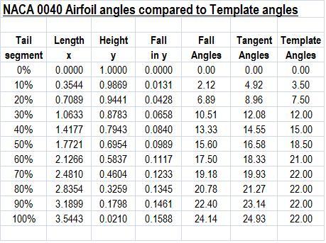
Seen that chart before, but makes more sense now, might go back and spit out some numbers for the TC ratio of 2.55, see how that looks.
But for now here is some more on NACA 040, I re did the chart to shift the 0 point to the peak and resize y axis to 1, along with the 10% gridlines along the x axis, this layout may be more familiar to people here.
I also calculated out a table to show the fall in height (or width) at each 10% segment, as the height is scaled to 1, it is easy to just multiply your starting height by the factor in the table to give you expected height at that point.
The fall represents the fall over the previous 10% of the curve and I have calculated out the fall angles, I also tabled the tangent angles at each 10% and then compared those to the template angles at the same point, not too far away, a close relative at the very least.

 |
|
|
|
|
The Following User Says Thank You to Tesla For This Useful Post:
|
|
|
01-21-2013, 11:09 AM
|
#393 (permalink)
|
|
Aero Deshi
Join Date: Jan 2010
Location: Vero Beach, FL
Posts: 1,065
Thanks: 430
Thanked 669 Times in 358 Posts
|
Quote:
Originally Posted by freebeard

The air molecule move, but they don't move from there to over there, they just move enough to bunch up against their neighbor, who moves over. In aggregate an acoustical wave. From the relativistic point of view of the moving vehicle, the air is blowing hard.
|
Ha, been sayin this for over a year.
My next step in the logic is after a car passes, we want the air to end up back exactly where it started and remaining stationary. (assuming a calm day)
If we can leave the air how we found it, in my mind it means the air gives back the energy it took to move it up and out of the way in the front part of the shape, so carefully crafting the rear is really essentially, an energy return system.
If the air gets pushed, or dragged forward, or made to spin, this would mean energy from the car had to be put into the air to get it to do so. This is a constant process, much like a fan needs the motor to keep moving a volume of air, the air moving to and fro around a car after it's passage thus represents the drag.
This sort of breaks it down into its simplest form how drag works and why the ideal shape is effective. Straying from the shape invariably means that either by pressure or skin drag, we have caused the air to move more than the ideal shape does and is thus less efficient. |
|
|
|
|
The Following 3 Users Say Thank You to ChazInMT For This Useful Post:
|
|
|
01-21-2013, 11:47 AM
|
#394 (permalink)
|
|
Master EcoModder
Join Date: Jun 2011
Location: Alabama
Posts: 625
Thanks: 40
Thanked 156 Times in 103 Posts
|
Freebeard-
Based on your chart, a shape with a height/length ratio of 1:4 is better than the template's ratio 1:2.5. Why then is the template only 1:2.5?
If I remember correctly, I think it has to do something with the 1:4 template being too impractical because it's so long. But I was wondering if there was another reason.
__________________
Aerospace Controls Engineer.
Currently driving a mostly stock 2014 Mitsubishi Mirage DE hatchback.
Last edited by HydroJim; 01-21-2013 at 11:55 AM..
|
|
|
|
|
01-21-2013, 04:04 PM
|
#395 (permalink)
|
|
Master EcoModder
Join Date: Aug 2012
Location: northwest of normal
Posts: 29,342
Thanks: 8,347
Thanked 9,110 Times in 7,523 Posts
|
ChazInMT -- Well, credit where due then.
HydroJim -- I'm not prepared to defend the chart, I just posted it so I wouldn't have to go back through the thread. I think its t/c is the inverse of fineness ratio. But now I've re-read the first 4 pages; relevant post include: The discussion seems to focus on NACA 6-series foils, and Clark-Y. cautions against using airfoil data when the pumpkin seed is the real optimum. Excessive length increases skin friction, but that's a small percentage of the total so it's fairly 'safe'. |
|
|
|
|
01-21-2013, 06:47 PM
|
#396 (permalink)
|
|
Master EcoModder
Join Date: Jan 2008
Location: Sanger,Texas,U.S.A.
Posts: 16,509
Thanks: 24,517
Thanked 7,436 Times in 4,817 Posts
|
2D vs 3D
Quote:
Originally Posted by HydroJim
Freebeard-
Based on your chart, a shape with a height/length ratio of 1:4 is better than the template's ratio 1:2.5. Why then is the template only 1:2.5?
If I remember correctly, I think it has to do something with the 1:4 template being too impractical because it's so long. But I was wondering if there was another reason.
|
The 2D flow drag minimum for struts or symmetrical wing sections is 1:4.
The 3D flow drag minimum for a streamline body of revolution which also respects W.A.Mair's 22-degree max.boat tail tangent angle is around 1:2.5.
1:2.1 is shown as the drag minimum for free flight in Hoerner's report but it violates the rear contour for flow attachment in a bluff body.
Some use the 1:4 contour in plan-view.
If you were doing something like Aptera or the Edison car,the 1:4 strut might be the way to go,as this would be pretty much 2D flow around the wheels.
__________________
Photobucket album: http://s1271.photobucket.com/albums/jj622/aerohead2/
|
|
|
|
|
01-21-2013, 07:40 PM
|
#397 (permalink)
|
|
Master EcoModder
Join Date: Feb 2012
Location: Australia
Posts: 355
Thanks: 5
Thanked 76 Times in 50 Posts
|
NACA 0039 compared to template
Ok, I think I'm just about done with this story.
Through a roundabout way I started looking at different t/c ratios to get the tail ratio of 1.78 and came up with this one:
Aspect ratio 2.5411:1
t/c is 0.393935
Tail ratio is 1.7800
I have tweaked the equation just a fraction to finish curve at 0, I have not done the overlay to the template (still need to work out how), but I think the numbers indicate it is damn close and probably closer than achieved in normal construction errors in scaling.
With an equation greater accuracy is possible by being able to extract data for any point on the curve.
It is just a fraction steeper at the start, then tapers out and curve accelerates again after the 80% mark, though this is pretty much irrelevant in the real world as even the keenest modders will finish their tails around this point.
The analysis of the angles may to some degree be irrelevant as I do not know exactly how the template angles were arrived at.
Below is the 0039 section, again scaled as best as I could on screen
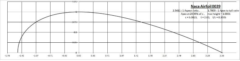

Just edited a couple of little details, minor bugs in spread sheet and adjustment to curve.
Last edited by Tesla; 01-22-2013 at 07:26 AM..
|
|
|
|
|
The Following User Says Thank You to Tesla For This Useful Post:
|
|
|
01-21-2013, 08:54 PM
|
#398 (permalink)
|
|
Aero Deshi
Join Date: Jan 2010
Location: Vero Beach, FL
Posts: 1,065
Thanks: 430
Thanked 669 Times in 358 Posts
|
Quote:
Originally Posted by freebeard
ChazInMT -- Well, credit where due then.
|
Credit is due to learning this stuff, I take no credit for the obvious, just glad to see others thinking alike. Everyone is always so hung up on the idea of the air moving over the car instead of the car through the air. Subtle but significant differance. |
|
|
|
|
01-22-2013, 12:27 PM
|
#399 (permalink)
|
|
Master EcoModder
Join Date: Aug 2011
Location: Warren, MI
Posts: 2,456
Thanks: 782
Thanked 669 Times in 411 Posts
|
Quote:
Originally Posted by ChazInMT
Ha, been sayin this for over a year.
My next step in the logic is after a car passes, we want the air to end up back exactly where it started and remaining stationary. (assuming a calm day)
If we can leave the air how we found it, in my mind it means the air gives back the energy it took to move it up and out of the way in the front part of the shape, so carefully crafting the rear is really essentially, an energy return system.
If the air gets pushed, or dragged forward, or made to spin, this would mean energy from the car had to be put into the air to get it to do so. This is a constant process, much like a fan needs the motor to keep moving a volume of air, the air moving to and fro around a car after it's passage thus represents the drag.
This sort of breaks it down into its simplest form how drag works and why the ideal shape is effective. Straying from the shape invariably means that either by pressure or skin drag, we have caused the air to move more than the ideal shape does and is thus less efficient.
|
This is so good I'm putting it in my sig. Thanks! 
__________________
He gave me a dollar. A blood-soaked dollar.
I cannot get the spot out but it's okay; It still works in the store
|
|
|
|
|
01-22-2013, 09:15 PM
|
#400 (permalink)
|
|
Master EcoModder
Join Date: Feb 2012
Location: Australia
Posts: 355
Thanks: 5
Thanked 76 Times in 50 Posts
|
Boattail sectional profile
Just playing with the numbers, I made up a table & chart to calculate the co-ordinates for a boat tail, chart below:
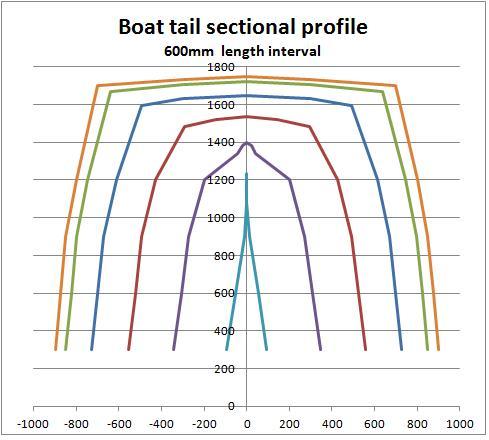
Just wanting to confirm some things:
1/ The width tapering is based from the vertical centreline of the vehicle, hence this will usually result in a shorter tail calculation than the taper from the roof as half vehicle width is usually less than height. This will then result in a much more rapid reduction in width than the reduction in height.
2/ Do the side taper & roof taper both have to have the same 0 point? Because of the difference in length, the tapers are going to be out of sync at the first 10% interval anyway, as the sides will runout well before the top. I ask this because some vehicles may have more taper on the sides, or top which may already conform to the first 15-20% of boattail taper.
The profiles are calculated from the NACA 0039 profile I put up earlier, but the chart is not perfectly scaled for visual dimensions, just representative. I've used an interval spacing of 600mm (2').
So the way I'm looking at this, if I was to build a trailer cap, as long as I stayed within the sectional paramaters, at the very worst it would be "stuffing the wake" and at best some or all surfaces will re-attach flow and reduce drag.
|
|
|
|
|
The Following User Says Thank You to Tesla For This Useful Post:
|
|
|