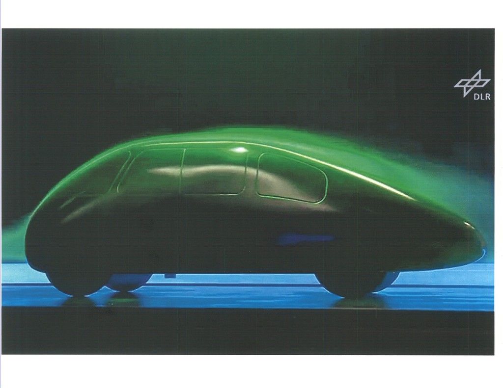
Quote:
Originally Posted by 3-Wheeler

Hi Phil,
I'm not trying to be picky, even though it could come across this way, but I do see some conflicting length/width ratios for the minimum airfoil shape posted at EcoModder.
The link below has some information that I will present below, and discuss.
http://ecomodder.com/forum/showthrea...rt-c-9287.html
The image below has sections of several minimum drag sources that show length/width ratios.
Starting from the top of the graphic, the minimum L/W ratio seems to be 2.5:1. I did not scale the graphic closely.
The second graphic shows a ratio of 1.0/.255 = 3.92 L/W
The third graphic clearly shows 2.5 L/W ratio
The C-version Streamlining Template shows a ratio of 4.72/2 = 2.36

I've looked on-line and did not find any other L/W information for subsonic winglets, and minimum drag, so this type of information may be limited to Hucho and other rare sources.
I do recall that you have mentioned that the minimum drag occurs at a L/W ratio of 2.5 many time before, yet some of the other sources do not match this, including the Streamlining Template.
Thanks, Jim. |
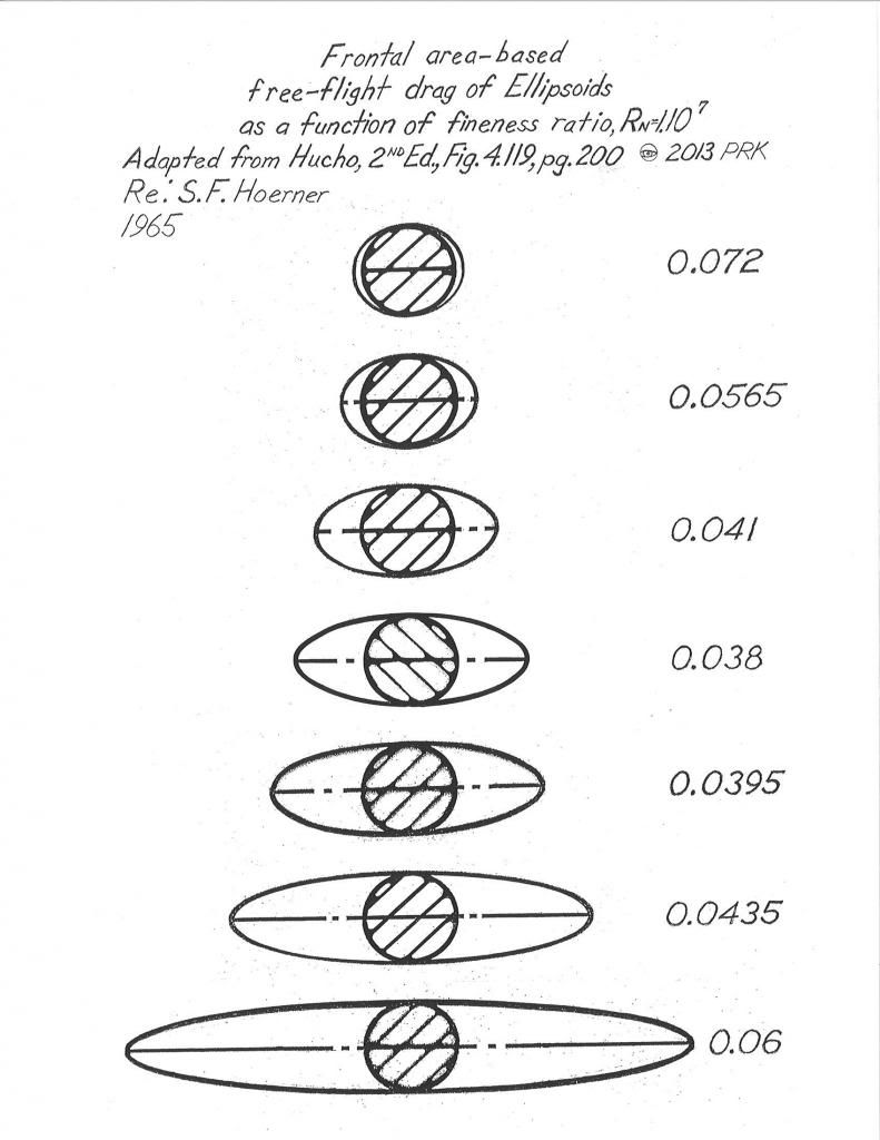
*Hucho is using Hoerner's research,and if you look at the source you find that 2.1:1 produces the lowest drag.This was from early NACA airship coastdown testing in New York.The enormous surface area of the airship envelope produced a thick turbulent boundary layer,which when sloughing off the rear tended to fill in a phantom tail area,built up from the shedding torroidal boundary layer.This dead air traveled along with the airship,effectively increasing it's L/D ratio.
*I think it was the 1929 ZMC 'tin bubble' metalclad airship which was built to one of these low ratios.It had very good speed for its power and frontal area but made the crew seasick,and you find airships built longer for flight stability.
Here's the 'tin bubble' at the bottom
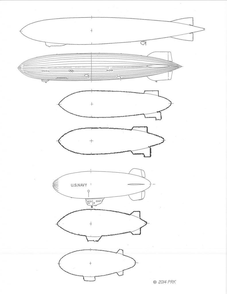
*The 2.1 ratio is low drag,but for a bluff body it exceeds Mair's 22-degree contour slope maximum and also Buchheim et al's 23-degree slope maximum.
*So as a half-body,in ground proximity,we need to stay near 22-23-degrees to protect the turbulent boundary layer from rapid pressure increases which trigger separation.
-------------------------------------------------------------------------
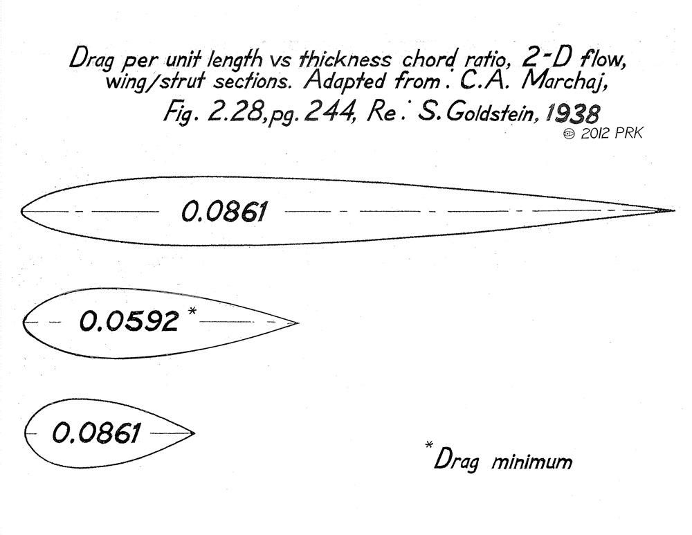
*For struts and airfoil sections the bottom of the friction drag/pressure drag 'bucket' occurs at L/thickness= 3.92 (also from Hoerner).So for mirror stalks,suspension fairings,wheel fairings,etc.. Also,we find that 3.92:1 has also been used successfully on record cars with plan-taper of the body only.The 1957 MG EX 181 uses it.
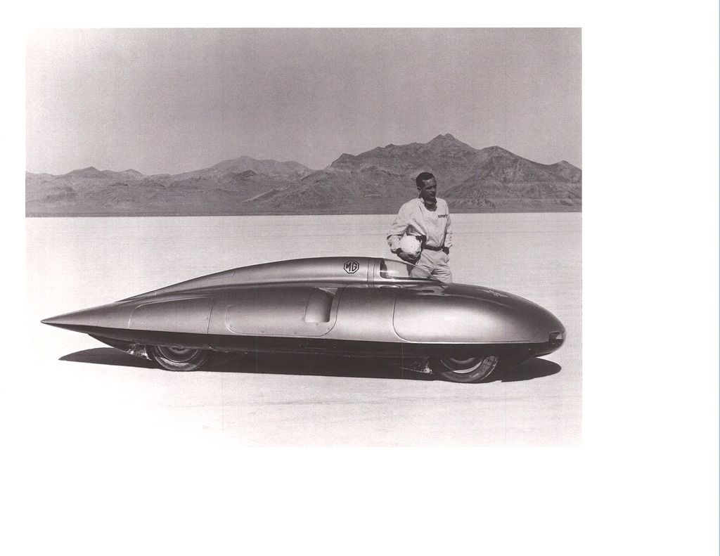
Here's the 'template',4th from bottom

Here is the strut/wing section research,published by Horner,from Goldsein's research
Also,we could theoretically use elliptical bodies of revolution as a basis of automobile bodies as their drag behaves exactly the same as streamline bodies EXCEPT that the windshields would be too steep to see out of,so we default to the 'bulbous','bug' nose equally low drag to get something we can see out of with glass.Hucho used the elliptical body L/D ratios in his drag example of the 1966 VW Beetle 1300,which again,show the drag minimum @ 2.5:1.
On the Aerodynamic Streamlining Template-II I used a 'faster' rear contour,closer to Buchheim et al.'s,from my college fluid dynamics text.It's close to a 2.5:1 L/D streamline body also,just a little more aggressive early in the contour,then actually more conservative at the end,with 21-degrees maximum slope.
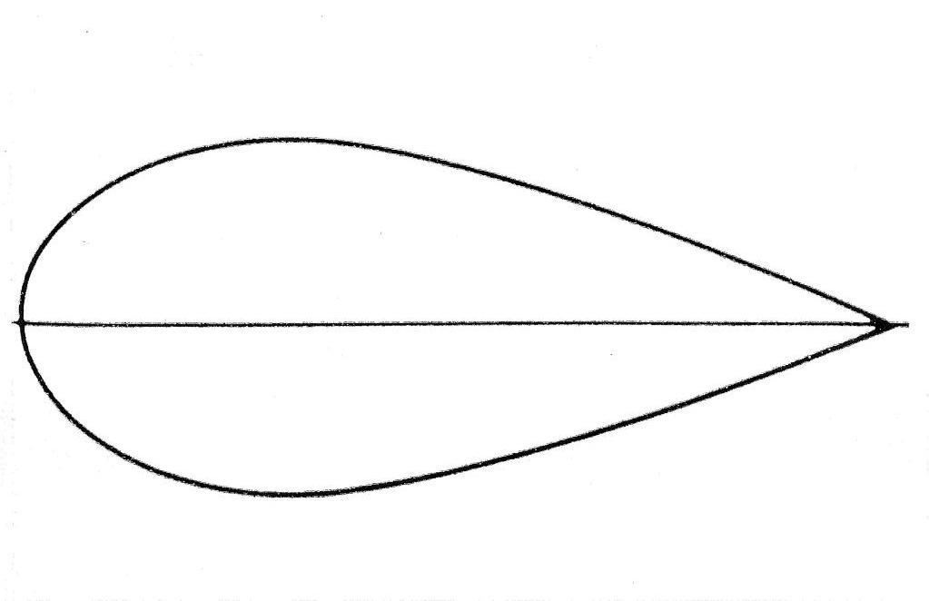
Here is the Buchheim et al. contour,developed in the VW wind tunnel.We shouldn't do anything more aggressive than this or we lose the game.
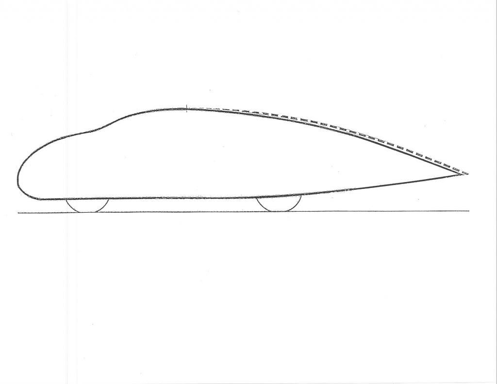
I kept the 'Template' conservative,as members are looking at maybe 800-man-hours to create an aft-body modification,and after all that you sure don't want to see separation back there.
