 05-30-2021, 03:48 AM
|
#11 (permalink)
|
|
EcoModding Lurker
Join Date: Mar 2021
Location: france
Posts: 14
Thanks: 1
Thanked 27 Times in 12 Posts
|
Quote:
Originally Posted by freebeard

If you're productizing the result, that's 10x the effort; so good on you, here's hoping....
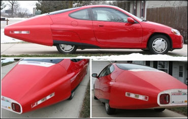
It's worth following Julian Edgar's advice. I think this is the best 'local' boat tail, I think it's on a different Insight now. Pic title says 'jims tail'.

Would your expected customers have a trailer light socket available? That would reduce rewiring effort. |
definitely. at this stage I want to assess the benefits only. if on an Insight which is already quite good in terms of wake given existing roof slant angle, boat tail allows reducing drag by 10-20%, I imagine that on this car this would be even more !
and yes if i go for the same version than prototype, i will install the trailer light socket so the mod is "plug and play" 
and I bought the book of Julian, inspiring indeed  !
|
|
|

|
|
The Following User Says Thank You to vianney For This Useful Post:
|
|
 Today Today
|
|
|
|
 Other popular topics in this forum...
|
|
|
|
 05-30-2021, 11:41 AM
|
#12 (permalink)
|
|
EcoModding Lurker
Join Date: Mar 2021
Location: france
Posts: 14
Thanks: 1
Thanked 27 Times in 12 Posts
|
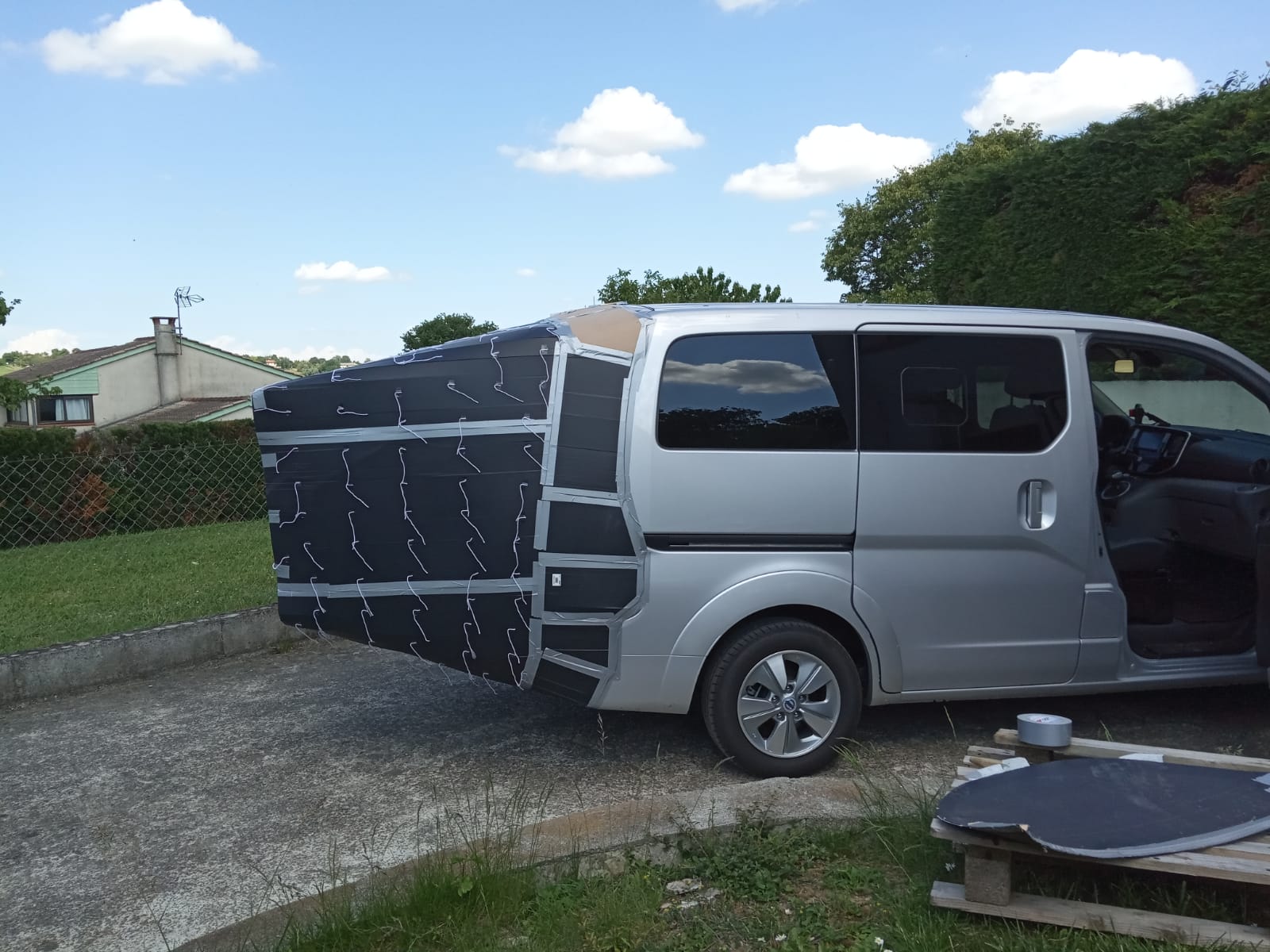
So, after a afternoon of testing with the boat-tail:

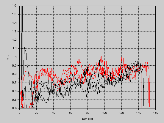
SCx shows an visible improvement, of around 0.1 to 0.15, which is not quite bad (around 15% drag reduction). Visible on both back and forth runs as expected.
red plots are without boat tail, and black ones with boat-tail installed. Abscissa is number of samples at target speed (90km/h)


So there is improvement, but not as much as expected.
Tuft testing reveals that flow is properly attached throughout the top side of the boat tail (12° angle), but on the sides this is not as good, and on the bottom side flow is completely detached, with strong recirculation bubble (tufts angled toward front)
tuft test videos (remove space between https and :// after pasting) are here :
https ://drive.google.com/drive/u/0/folders/145GXU43Vr1g5UUUGFSZIjnWNE0dYWV1b
I redid the tuft testing after having installed the undertray and the rear wheel cover (assuming the undertray would provide more stable flow undercar, and same for rear wheel cover on the side).
However the tufts remained the same.
For the car side, I had checked previously that flow are conveniently attached up to the rear of the car.
So most probable cause is:
- for underside, the undertray is not efficient and/or the boat tail angle is too important (it is around 15°, while literature consensus is more around 7°). Problem of the undertray is that the transverse bar is so low that if I want the diffuser to go from the bottom of that bar up to the rear bumper it requires an angle of 15° for the diffuser, which is too large according to literature.
- for side, maybe the slant angle is too large (I think it is around 20° in average). there is not recirculation (tufts general direction is aftwards), but it is visible that the flow is perturbated by something.
I will attempt with some friends to add smoke in the boundary layer to see how it develops over the car. |
|
|

|
|
The Following 4 Users Say Thank You to vianney For This Useful Post:
|
|
 05-30-2021, 01:20 PM
|
#13 (permalink)
|
|
Master EcoModder
Join Date: Aug 2012
Location: northwest of normal
Posts: 29,310
Thanks: 8,336
Thanked 9,095 Times in 7,512 Posts
|
15% is not bad if there's obvious room for improvement.
If you flatten the angle of the undertray, it will approach the departure angle. Could the it run above the traverse bar, with an airfoil section added to it?
If the plan is a flat bulkhead at the truncation, there exist boxed cavities (my favorite example it the Cobra Daytona Coupe). Even if the gain is marginal a concave surface would allow lightening the structure. Maybe a little harder to fabricate.
__________________
.
.Without freedom of speech we wouldn't know who all the idiots are. -- anonymous poster
___________________
.
.Impossible is just something we haven't done yet. -- Langley Outdoors Academy
|
|
|

|
 05-30-2021, 05:35 PM
|
#14 (permalink)
|
|
Banned
Join Date: Nov 2017
Location: Australia
Posts: 2,060
Thanks: 107
Thanked 1,608 Times in 1,137 Posts
|
Good job on tufting.
I wouldn't worry too much about the side flows, but obviously the underside is unacceptable. Why not put a temporary underside panel that is horizontal and see if it gets attached flow? If it doesn't, you then know the issues are ahead of it, not its angle.
|
|
|

|
|
The Following User Says Thank You to JulianEdgar For This Useful Post:
|
|
 06-01-2021, 11:08 AM
|
#15 (permalink)
|
|
Master EcoModder
Join Date: Jan 2008
Location: Sanger,Texas,U.S.A.
Posts: 16,483
Thanks: 24,508
Thanked 7,436 Times in 4,817 Posts
|
' angles'
https://www.pinterest.com/pin/168533211025982771/https://www.pinterest.com/pin/556827941407233444/Technically, you want 'curves' not angles, at least until you've transitioned from the straight plank sides into the critical slope angle. Just as you've drawn for the side elevation.
The sides need to be exactly like the top, when viewed from above.
Only you can tell how much the diffuser angle will have to be compromised.
18% body length diffusers are never more than around 4-degrees upsweep.
The low drag diffusers are even 'slower' in angle if 'straight-flat'. They can withstand higher angles if gently and progressively curved, as in the Volkswagen 2000 concept of 1980. Much like your drawing.
I realize that is complicates fabrication by orders of magnitude, but in order to protect the boundary layer, there cannot be any 'kinks' or pressure 'spikes'.
The Evalia is reported at Cd 0.31. It's frontal area is going to be in the neighborhood of 2.9 meters-squared.
It's rated at 165- km highway in 'warm' weather.
391- Wh/mile ( 242.4 Wh/ km )
If we knew the exact speed at which your Evalia registered 242 Wh/km, that would be a good test speed.
------------------------------------------------------------------------------------
Dirty math suggests:
* Cd 0.31 OEM
* Cd 0.304 with rear skirts
* Cd 0.269 with smooth rear belly section and 'slow' diffuser
* Cd 0.17 with boat tail.
* a 45% drag reduction
* maybe 195-km range
You'd have to have the more complex geometry.
Here's how Union-Pacific Railroad handled the more complex surfaces in 1934. See link at top
__________________
Photobucket album: http://s1271.photobucket.com/albums/jj622/aerohead2/
Last edited by aerohead; 06-01-2021 at 12:52 PM..
Reason: add photo link data
|
|
|

|
|
The Following User Says Thank You to aerohead For This Useful Post:
|
|
 06-02-2021, 11:32 AM
|
#16 (permalink)
|
|
Aero Wannabe
Join Date: Dec 2007
Location: NW Colo
Posts: 738
Thanks: 705
Thanked 219 Times in 170 Posts
|
Getting good flow on the bottom of your boattail may be difficult in the real world. If you ever have to drive up or down a ramp the back end of the boattail can drag on the ground.
https://en.wikipedia.org/wiki/Trailer_tail
These are sometimes used on semi truck (tractor-trailers) trailers here in the U.S. It is compromise toward utility over aerodynamic optimization.
__________________
60 mpg hwy highest, 50+mpg lifetime
TDi=fast frugal fun  https://ecomodder.com/forum/showthre...tml#post621801

Quote:
Originally Posted by freebeard

The power needed to push an object through a fluid increases as the cube of the velocity. Mechanical friction increases as the square, so increasing speed requires progressively more power.
|
|
|
|

|
|
The Following User Says Thank You to COcyclist For This Useful Post:
|
|
 06-06-2021, 08:15 AM
|
#17 (permalink)
|
|
EcoModding Lurker
Join Date: Mar 2021
Location: france
Posts: 14
Thanks: 1
Thanked 27 Times in 12 Posts
|
Quote:
Originally Posted by aerohead

Technically, you want 'curves' not angles, at least until you've transitioned from the straight plank sides into the critical slope angle. Just as you've drawn for the side elevation.
The sides need to be exactly like the top, when viewed from above.
Only you can tell how much the diffuser angle will have to be compromised.
18% body length diffusers are never more than around 4-degrees upsweep.
The low drag diffusers are even 'slower' in angle if 'straight-flat'. They can withstand higher angles if gently and progressively curved, as in the Volkswagen 2000 concept of 1980. Much like your drawing.
I realize that is complicates fabrication by orders of magnitude, but in order to protect the boundary layer, there cannot be any 'kinks' or pressure 'spikes'.
The Evalia is reported at Cd 0.31. It's frontal area is going to be in the neighborhood of 2.9 meters-squared.
It's rated at 165- km highway in 'warm' weather.
391- Wh/mile ( 242.4 Wh/ km )
If we knew the exact speed at which your Evalia registered 242 Wh/km, that would be a good test speed.
------------------------------------------------------------------------------------
Dirty math suggests:
* Cd 0.31 OEM
* Cd 0.304 with rear skirts
* Cd 0.269 with smooth rear belly section and 'slow' diffuser
* Cd 0.17 with boat tail.
* a 45% drag reduction
* maybe 195-km range
You'd have to have the more complex geometry.
Here's how Union-Pacific Railroad handled the more complex surfaces in 1934. See link at top
|
here is the excel sheet I used to calibrate drag coefficients (rolling resistance, cd, etc)
docs.google.com/spreadsheets/d/1wZTI-nX2AWMz4ppH0gTCxHLHz6gaMt8Z/edit#gid=190811041
average consumption at 103km/h (true speed) is 244Wh/km (avg of 3 measures). The Cd I get is more around 0.37 (actually 0.31 is the Cd of the leaf which is much more aerodynamic than the env200, frontal area set apart, so 0.31 I thought anyway it was a bit underestimated, altough there may be as well some economies of scale).
I will try to tuft-test the undertray to see if flow is detached already at this stage. Problem is that the transverse bar is very low hanging and if I attempt to put a 5° rigid slope upwards I'm pretty sure it will scratch at every bumper  . But I could setup something flexible so that it the shape can be designed for target speed and adapt in other situations. |
|
|

|
|
The Following User Says Thank You to vianney For This Useful Post:
|
|
 06-06-2021, 08:38 AM
|
#18 (permalink)
|
|
EcoModding Lurker
Join Date: Mar 2021
Location: france
Posts: 14
Thanks: 1
Thanked 27 Times in 12 Posts
|
I also added in the tuft test videos folder the one done with boat tail and wheel skirt.
compared to without wheel skirt, the tufts located just below the low horizontal tape line behave much better (at least they do not move in the forward direction ^^)
I should do some data logging in this configuration to see what drag reduction i achieve.
Last edited by vianney; 06-06-2021 at 10:00 AM..
|
|
|

|
|
The Following User Says Thank You to vianney For This Useful Post:
|
|
 06-09-2021, 10:42 AM
|
#19 (permalink)
|
|
Master EcoModder
Join Date: Jan 2008
Location: Sanger,Texas,U.S.A.
Posts: 16,483
Thanks: 24,508
Thanked 7,436 Times in 4,817 Posts
|
perturbed side flow
Since you mentioned this, I re-visited the research done on the Ahmed body.
Some data points:
* when the rear is modified, this new 'aft-body' constitutes 21.8% of total body length
1) @ zero-degree rear downslope only, Cd 0.25
2) @ 5-degree downslope only, Cd 0.233
3) @ 9-degrees downslope only, Cd 0.229
4) @ 12.5-degrees downslope only, Cd 0.23
5) @ 15-degrees downslope only, Cd 0. 236
6) @ 20-degrees downslope only, Cd 0.253
7) @ 25-degrees downslope only, Cd 0.287
--------------------------------------------------------------------------------------
8) #7 plus a 10-degree upswept diffuser, Cd 0.262
9) #7 and #8, plus 10-degree plan-view boat-tailing. Cd 0.214
--------------------------------------------------------------------------------------
* As the numbers reveal, the top rear slant initially lowers drag until just before the 20-degree angle, then rises above the original Cd.
* Adding the diffuser lowers drag, although it's still above the original Cd.
* It isn't until the side boat-tailing is introduced that, drag finally falls below the original Cd, for an overall 14.4% drag reduction, @ Cd 0.214.
--------------------------------------------------------------------------------------
* This 25-degree, 10-degree, 10-degree tail relies on a series of vortices, in 3- planes, attacking one another, to burst each other.
-------------------------------------------------------------------------------------
If it were true that the side flow on your tail WAS compromised, the above illustration might provide insight into the performance.
--------------------------------------------------------------------------------------
I did a rough calculation using the as-shown, truncated W.A. Mair boat tail:
* Ignoring the wheels, the wake area was reduced to 15.38 square-feet ( 1.428 meters-squared. A 51% reduction.
* With rear belly pan, 'slow' diffuser, rear wheel skirts, and tail, we have a probability for a 45% drag reduction.
__________________
Photobucket album: http://s1271.photobucket.com/albums/jj622/aerohead2/
|
|
|

|
 07-22-2021, 07:11 AM
|
#20 (permalink)
|
|
Master EcoModder
Join Date: May 2009
Location: Australia
Posts: 1,510
Thanks: 325
Thanked 453 Times in 320 Posts
|
Quote:
Originally Posted by vianney

average consumption at 103km/h (true speed) is 244Wh/km (avg of 3 measures). The Cd I get is more around 0.37 (actually 0.31 is the Cd of the leaf which is much more aerodynamic than the env200, frontal area set apart, so 0.31 I thought anyway it was a bit underestimated, altough there may be as well some economies of scale).
|
Vans are more aerodynamic than people think, my Renault Trafic had an ECO version that was 0.31 vs the stock version of 0.33. 0.37 was the old boxy shape Ford Transit. There's almost no way the ENV is that bad.
I'm currently trying to find an ENV of my own, I'll be doing an aero trailer rather than a boat tail.
|
|
|

|
|