08-02-2024, 04:27 AM
|
#91 (permalink)
|
|
aero guerrilla
Join Date: Oct 2008
Location: Warsaw, Poland
Posts: 3,756
Thanks: 1,348
Thanked 756 Times in 478 Posts
|
Quote:
Originally Posted by JohnForde

First test. No success. 30 miles each way.
1.55mi/kWh northbound
1.85 southbound.
Stock Zevo averages 1.85
Pictures
|
Hard to believe that a boattail like the one in your pics wouldn't have any effect 
What speed were you testing at? For the tests you might want to try a slightly higher speed than you would normally be driving, just to exaggerate the results.
When I tested my aero mods I did passes at 70 and at 100 km/h to see the difference.
__________________
e·co·mod·ding: the art of turning vehicles into what they should be
What matters is where you're going, not how fast.
"... we humans tend to screw up everything that's good enough as it is...or everything that we're attracted to, we love to go and defile it." - Chris Cornell
 [Old] Piwoslaw's Peugeot 307sw modding thread
|
|
|

|
|
The Following User Says Thank You to Piwoslaw For This Useful Post:
|
|
 Today Today
|
|
|
|
 Other popular topics in this forum...
|
|
|
|
|
08-02-2024, 02:30 PM
|
#92 (permalink)
|
|
AKA - Jason
Join Date: May 2009
Location: PDX
Posts: 3,606
Thanks: 327
Thanked 2,154 Times in 1,457 Posts
|
Quote:
Originally Posted by Piwoslaw
Hard to believe that a boattail like the one in your pics wouldn't have any effect
What speed were you testing at? For the tests you might want to try a slightly higher speed than you would normally be driving, just to exaggerate the results.
When I tested my aero mods I did passes at 70 and at 100 km/h to see the difference. |
What looks aerodynamic sometimes is not. The 18 degree angle is likely still too large and flow is separating. (Which is why the commercial version has a 11 degree angle) |
|
|
|
|
The Following User Says Thank You to JSH For This Useful Post:
|
|
|
08-03-2024, 12:55 AM
|
#93 (permalink)
|
|
EcoModding Lurker
Join Date: Nov 2023
Location: MN
Posts: 93
Thanks: 35
Thanked 99 Times in 63 Posts
|
The current iteration has 14 degree doors. Still no effect.
200 miles in to my day todaythe coroplast cuff failed. It is just too much to ask for from Gorilla tape.
It occurs to me that the first thing I should do is tuff test the stock cuff. It is 12 inches at about 17 degrees.
Back to the drawing board to re fabricate the cuff. I'm remembering that I have excellent structure on which to build. I am considering aluminum sheet, maybe 3/16". or possibly that hard plastic they use in cutting boards.
The other urgent piece is replacing the tail lights with new lights on the step bumper. This will allow full height doors.
At a wedding this weekend in western South Dakota. Back working on the project at home in St Paul Tuesday.
|
|
|
|
|
The Following User Says Thank You to JohnForde For This Useful Post:
|
|
|
08-03-2024, 11:13 AM
|
#94 (permalink)
|
|
Master EcoModder
Join Date: Aug 2012
Location: northwest of normal
Posts: 29,002
Thanks: 8,231
Thanked 9,003 Times in 7,437 Posts
|
Quote:
|
I am considering aluminum sheet, maybe 3/16". or possibly that hard plastic they use in cutting boards.
|
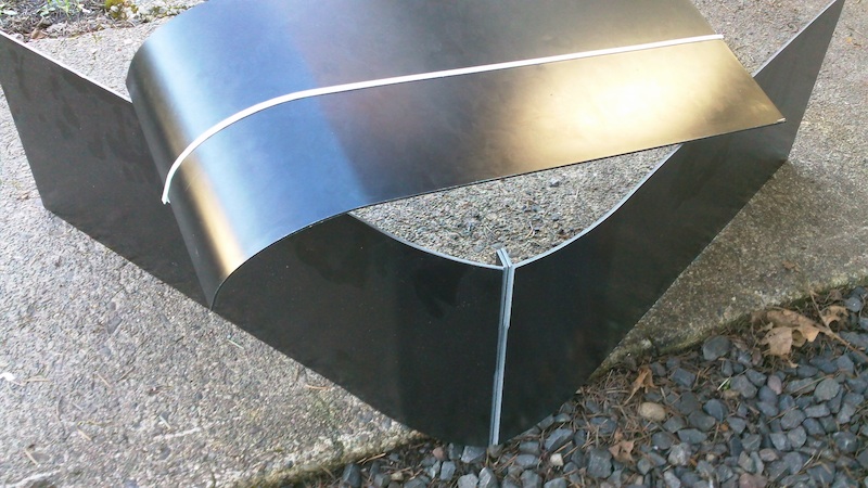
Polymetal/Alumapanel/Maxmetal. The sample was sheared rolled and braked by hand. A 6-7ft roller could be improvised with three pipes and skate board bearings.
I learned that a braked angle should be scored on the inside to crush the plastic core, as you can see.
__________________
.
.Without freedom of speech we wouldn't know who all the idiots are. -- anonymous poster
________________
.
.Because much of what is in the published literature is nonsense,
and much of what isnt nonsense is not in the scientific literature.
-- Sabine Hossenfelder
|
|
|
|
|
The Following User Says Thank You to freebeard For This Useful Post:
|
|
|
08-03-2024, 02:28 PM
|
#95 (permalink)
|
|
AKA - Jason
Join Date: May 2009
Location: PDX
Posts: 3,606
Thanks: 327
Thanked 2,154 Times in 1,457 Posts
|
Quote:
Originally Posted by JohnForde
The current iteration has 14 degree doors. Still no effect.
|
If I understand correctly the stock rear trim is 17 degrees. Your structure is 14 degrees, and you have a taped panels to connect the two angles.
There is no effect because the flow is separating before it reaches your added structure. The stock 17 degree angle is too much. |
|
|
|
|
08-04-2024, 12:51 PM
|
#96 (permalink)
|
|
Master EcoModder
Join Date: Jul 2011
Location: Ann Arbor, Michigan
Posts: 4,193
Thanks: 135
Thanked 2,815 Times in 1,976 Posts
|
Since this is the latest box tail / box cavity thread I'll post this here.
Looks to be part of an expandable camper scheme.
Next Honda Element?
https://tflcar.com/2024/08/ask-natha...otive-messiah/
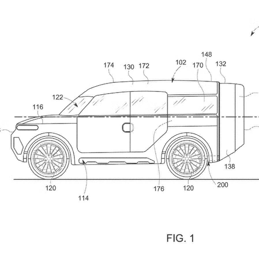
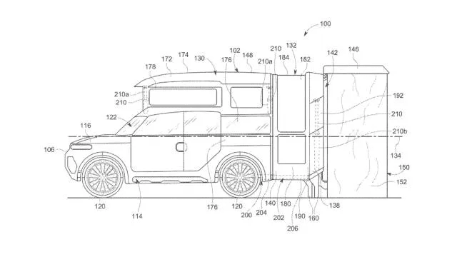
Just looking at the angles, the lower departure angle looks to be for off-road and NOT aerodynamics.
__________________
George
Architect, Artist and Designer of Objects
2012 Infiniti G37X Coupe
1977 Porsche 911s Targa
1998 Chevy S-10 Pick-Up truck
1989 Scat II HP Hovercraft
You cannot sell aerodynamics in a can............
|
|
|
|
|
The Following 2 Users Say Thank You to kach22i For This Useful Post:
|
|
|
08-04-2024, 01:06 PM
|
#97 (permalink)
|
|
Master EcoModder
Join Date: Jul 2011
Location: Ann Arbor, Michigan
Posts: 4,193
Thanks: 135
Thanked 2,815 Times in 1,976 Posts
|
Quote:
Originally Posted by JSH
If I understand correctly the stock rear trim is 17 degrees. Your structure is 14 degrees, and you have a taped panels to connect the two angles.
There is no effect because the flow is separating before it reaches your added structure. The stock 17 degree angle is too much.
|
Interesting observation, and seems to match what has been posted in the forum previously.
2009
Maximum angle for boat tail?
https://ecomodder.com/forum/showthre...tail-8927.html
Quote:
Originally Posted by Bicycle Bob
Speed affects the Reynold's number, which has a small effect over the range we are concerned with. The classic answer to afterbody taper is 15 deg. top and sides, and 4 on the bottom. Those are average best numbers, but can be affected by many other factors.
|
I know first hand how frustrating things can be when trying new things.
Hang in there JohnForde.
Is there any way to change materials to something clear like acrylic so that it is continuous along the sides?
I'm just thinking that something less than half the extension you have now with similar angles three sides and full length at the sides will be more effective.
2005
New Boat Tail Design Could Improve Class 8 Truck Fuel Economy by 10%
https://www.greencarcongress.com/200...at_tail_d.html
Quote:
|
The Clarkson researchers evaluated more than 100 different design geometries, where cavity length, boat tail angle, and inset from the trailer edge were varied at yaw angles up to 9 degrees. They found that the optimum geometry of a four-foot device with a boat tail angle of 10° and no inset could reduce the indicated drag coefficient up to CD=0.12.
|

__________________
George
Architect, Artist and Designer of Objects
2012 Infiniti G37X Coupe
1977 Porsche 911s Targa
1998 Chevy S-10 Pick-Up truck
1989 Scat II HP Hovercraft
You cannot sell aerodynamics in a can............
Last edited by kach22i; 08-04-2024 at 01:14 PM..
|
|
|
|
|
The Following User Says Thank You to kach22i For This Useful Post:
|
|
|
08-05-2024, 11:34 AM
|
#98 (permalink)
|
|
EcoModding Lurker
Join Date: Nov 2023
Location: MN
Posts: 93
Thanks: 35
Thanked 99 Times in 63 Posts
|
Current plan: Cuff using HDPE. Cuff is 11 degrees and 18"L.
Doors of 55", just reaching 48" behind the bumper (legal). They can adjust the second break angle. Or just stay at 11 deg. I am hoping to tuft test and maintain attachment at 16 or 18 deg. This is to follow Aeroheads advice that drag is porportional to wake size, or as I call it, the 'aperture'.
Once I succeed on the basic tail I will put tail lights at the tips and add a foldable or detachable polycarbonate extension to ~96".
Last edited by JohnForde; 08-05-2024 at 11:45 AM..
|
|
|
|
|
The Following 3 Users Say Thank You to JohnForde For This Useful Post:
|
|
|
08-05-2024, 12:45 PM
|
#99 (permalink)
|
|
Master EcoModder
Join Date: Jan 2008
Location: Sanger,Texas,U.S.A.
Posts: 16,407
Thanks: 24,473
Thanked 7,410 Times in 4,800 Posts
|
' first test '
It's a 'success' because you've obtained valuable data you couldn't otherwise have obtained.
'Armchair-quarterbacking', I'd say that the first issue involves the 'cuff.' Let's say, it's a 12-inch radius. Imagine a 'clock face' 24-inches in diameter, laid directly over it.
If the flow over the roof and sides reaches the beginning of the 'cuff' at 12:00 o'clock, you're going to experience flow separation when the air reaches '4-seconds' past 12:00.
'Technically', this is where your attachment point would be.
Whatever angle chosen, it would begin at this location.
--------------------------------------------------------------------------------------
On simple, 'van-like' vehicles, with straight sides and roof, the lowest drag for 'straight angle', 'sharp-corner', boat-tailing has occurred with rather 'shallow' angles.
* The Ahmed body achieves minimum Cd at 9-degrees slope.
* The Howell et al. Windsor body 'sharp-cornered tail achieves an 18% drag reduction with 8-degrees top & sides, flat bottom.
* ATDynamics Trailer Tail uses 12.5-degrees top & sides, flat floor.
* Lawrence Livermore National Laboratory used 11-degrees, top & sides, with flat floor.
* I do not possess 'true-length' images for Clarkson University's tails, but they'd be worth the 'hunt.'
--------------------------------------------------------------------------------------
It seems logical, that changing from 14-degrees, off the 4-second location on the 'cuff', to perhaps 12.5-degrees, would get you in attached flow territory.
__________________
Photobucket album: http://s1271.photobucket.com/albums/jj622/aerohead2/
|
|
|
|
|
08-05-2024, 01:02 PM
|
#100 (permalink)
|
|
Master EcoModder
Join Date: Jan 2008
Location: Sanger,Texas,U.S.A.
Posts: 16,407
Thanks: 24,473
Thanked 7,410 Times in 4,800 Posts
|
16-18-degrees
Quote:
Originally Posted by JohnForde
Current plan: Cuff using HDPE. Cuff is 11 degrees and 18"L.
Doors of 55", just reaching 48" behind the bumper (legal). They can adjust the second break angle. Or just stay at 11 deg. I am hoping to tuft test and maintain attachment at 16 or 18 deg. This is to follow Aeroheads advice that drag is porportional to wake size, or as I call it, the 'aperture'.
Once I succeed on the basic tail I will put tail lights at the tips and add a foldable or detachable polycarbonate extension to ~96".
|
1) I'd focus on 'attached flow' as without it, there's no pressure recovery, and the 'wake' begins exactly at the point of separation.
2) If you can 'sneak up' on the 'cuff' with an 11-degree angle, and see 'where' it 'touches' the 'cuff,' that ought to be the actual 'origin' of the whale tail.
3) Don't rely on the 'cuff' itself for any meaningful pressure recovery. It's radius just isn't up to the task.
4) If you can get 11-degrees, just stay with it.
5) Any 'breaks' to a 'steeper' angle will be the trigger for an adverse pressure gradient that will kill flow attachment right then and there.
6) The new 'wake' size will be a function of the length of the tail. With drafting instruments, and a scale-drawing, you can ascertain what the new wake area will be, before you begin.
7) Another 'fly in the ointment' is vortex-induced drag. In 1984, P.W. Bearman reported on research of a proto-Windsor body of Cd 0.262 as a 'squareback'.
As rear downslope was introduced, creating a 'fastback', vortex drag initiated immediately, raising the Cd to as high as 0.37, depending on the angle.
__________________
Photobucket album: http://s1271.photobucket.com/albums/jj622/aerohead2/
Last edited by aerohead; 08-05-2024 at 01:45 PM..
Reason: typo
|
|
|
|
|