 10-14-2015, 03:43 PM
|
#2181 (permalink)
|
|
Permanent Apprentice
Join Date: Jul 2010
Location: norcal oosae
Posts: 523
Thanks: 351
Thanked 318 Times in 215 Posts
|
After reading the FRM manual and the DSpic4011 manual some more, I think I understand a bit more about how the DS pic deals with simultaneous AtoD conversion.
What I didn't understand was how the CHx's were assigned to the analog inputs. For some reason I thought they were all like CH0, which allows any analog input to be assigned. NOT SO.  Apparently Ch1, Ch2, and Ch3 can only be assigned to AN0, AN1, AN2 OR AN3, AN4, AN5 respectively. page 416 FRM
Paul probably said that previously, but I guess I didn't get it or didn't want to listen. 
What does this mean from a hardware perspective? It means that for the very critical current1 and current2 feedbacks used for FOC and Sensorless code should not be changed, according to configurations. The current sensors are etched in stone, tied to pins 3 and 4.
Pin2 is AN0 and is tied to CH1 through the simultaneous sampling definition. The only choice left is CH0, which can be pretty much any analog input.
Just so there's some semblance of sanity, I suggest that this input be AN3. Then all critical timing issues would be handled by analog inputs AN0 > AN3. If anyone comes up with some cool device that requires time-critical sampling, that part of the board will be a known set entity.
This presents a problem regarding the resolver input, which I was hoping could simply plug into the same pins the encoder (QEI) plugs into. These are pins 5,6 and 7; also tied to analog inputs AN3, AN4, and AN5. As the resolver driver is currently built, motor temperature is AN3, resolver sin is AN4 and resolver cos is AN5. To work properly sin and cos should be sampled simultaneously, which cannot be done unless things were re-defined so AN3, AN4, and AN5 were simultaneously sampled. This would be really dumb, because now the current couldn't be sampled. I am totally against re-defining input ports on the fly, because I think it would lead to reliability problems. Secondly, I'm pretty sure that the resolver will work together with the current inputs for FOC. This can potentially save serious computing time and I'm working on that end. 
This means I'll have to re-do the resolver-driver board. It also will require some main board changes. These can be done with a number of options:
1) re-route inputs using jumpers for different configurations.
2) add a set of connections for resolver input from an add-on board and a way the ensure both a resolver and encoder can't be plugged in at the same time.
3) add the circuits of the resolver driver to the main board.
In any case, I think it would be best to move the throttle input to AN6, AN7, or AN8 where it can hang out with other throttle and temperature inputs. AN0 could also be used for another current sensor to help out with the sensorless control stuff.
For testing purposes, I'm just going to go with option1. It'll be a bit ugly, and hopefully noise won't be too much of a problem. By using this method, I'll also have a free analog input pin that I can use for the double throttle setup I was talking about.
- E*clipse
|
|
|

|
|
The Following User Says Thank You to e*clipse For This Useful Post:
|
|
 Today Today
|
|
|
|
 Other popular topics in this forum...
|
|
|
|
|
10-14-2015, 04:08 PM
|
#2182 (permalink)
|
|
Permanent Apprentice
Join Date: Jul 2010
Location: norcal oosae
Posts: 523
Thanks: 351
Thanked 318 Times in 215 Posts
|
Paul - quick question regarding all the non time critical AtoD's.
Where in the code do you get these non-critical values? I'm lost...
Is this connected to this structure? 
Code:
volatile realtime_data_type RTData = {0,0,0,0,0,0,0,0,0,0,0,0,0};
and this function? If so, it's not called in code.
Code:
void FetchRTData() {
Is this assigned semi-automatically? Maybe through this?
Code:
RTData.throttle = throttle;
Or does this merely put a variable in an array structure?
*****edit*****
I've found some "normal code" in a large block of commented out code. Are you just not looking at throttle and temperature right now during sensorless testing??
***************
I've done lots of DSPic AtoD, and I'm very confused...
Thanks for any enlightenment! 
E*clipse
Last edited by e*clipse; 10-14-2015 at 04:32 PM..
Reason: another possibility??
|
|
|
|
|
10-14-2015, 06:24 PM
|
#2183 (permalink)
|
|
Master EcoModder
Join Date: Sep 2010
Location: Saskatoon, canada
Posts: 1,488
Thanks: 746
Thanked 565 Times in 447 Posts
|
Quote:
Originally Posted by e*clipse

*****edit*****
I've found some "normal code" in a large block of commented out code. Are you just not looking at throttle and temperature right now during sensorless testing??
***************
|
Paul DID say that he was 'IGNORING THE THROTTLE' in a previous post .. when I had all of the fun with my potentiometer.
I think you found the *REAL* code for reading the throttle and temperatures |
|
|
|
|
The Following 2 Users Say Thank You to thingstodo For This Useful Post:
|
|
|
10-14-2015, 06:36 PM
|
#2184 (permalink)
|
|
Permanent Apprentice
Join Date: Jul 2010
Location: norcal oosae
Posts: 523
Thanks: 351
Thanked 318 Times in 215 Posts
|
Quote:
Originally Posted by thingstodo
Paul DID say that he was 'IGNORING THE THROTTLE' in a previous post .. when I had all of the fun with my potentiometer.
I think you found the *REAL* code for reading the throttle and temperatures
|
Ahhhh! Ok.
I just thought Paul had some slick trick to do this and for some reason I just wasn't comprehending it. 
Cool! Thanks a bunch!
- E*clipse |
|
|
|
|
The Following User Says Thank You to e*clipse For This Useful Post:
|
|
|
10-14-2015, 06:55 PM
|
#2185 (permalink)
|
|
PaulH
Join Date: Feb 2008
Location: Maricopa, AZ (sort of. Actually outside of town)
Posts: 3,832
Thanks: 1,362
Thanked 1,202 Times in 765 Posts
|
I wasn't using the FetchRTData() at all at the moment. And thingstodo is right. I just blocked out all the throttle code during the debugging just so he could eliminate the "throttle out of range" error that was being caused by a bad POT.
I"m just about done with a simple to assemble (only a hand drill required) TO-247 all through-hole (with optional 1206 surface mount) AC controller that should be good to about 50kW assuming you can push 100amp through a high end TO-247 mosfet. And it has a boost front end. The cost (excluding inductor) should be around $250 or so for everything. The control board is 2 layer (phew!) so it will be a lot cheaper. No wiring really. The TO247 mosfets or IGBTs solder directly to the driver board AND the power board and the driver board solders (or gets plugged in) to the control board. At the moment I have it as AN0 = CH1 = resolver 1, AN1 = CH2 = current 1, an2 = ch3 = current 2.
Then, the all flexible CH0 can be
AN3 = index/resolver2
an6 = brake
an7 = temperature
an8 = throttle
So, it's a commitment to do resolver1 even if you aren't using a resolver. But that's OK. brake, temperature, and throttle are all "slowly" changing quantities. You could do "an0, an1, an2, an3" 7/8ths of the time, and then, 1/8th of the time switch between an6, an7, and an8. something like that.
I have never had any trouble changing ch0 on the fly (I've done it quite a bit on other projects for my job). I think it's designed for that. Similarly, you can change the PWM period every single cycle without any glitches too. I would be interested in knowing if it could cause a problem. I know that it's pretty standard practice to change A/D channels on the fly. The brushed DC controller does that and hasn't ever had any problems, and that's with the lowly 8 bit atmega168.
It's meant to be a ghetto version that just gets the boosting done, but isn't a total solution for everything. There's no voltage monitoring. Just a pot that you set the multiple of the input voltage. The extra pwm can be run at a higher frequency, since it's a different microcontroller. It's just a dspic30f2010 or something like that, so only a couple extra dollars. And it doesn't need a crystal, because it has no communication between it and the main microcontroller. The only message is a low signal from the main micro to the small cheap micro means there is a fault somewhere. At startup, the moment the fault clears signals the message to the small micro that it can go ahead and ramp up the boost voltage to the multiple specified by the POT. If there's a hardware fault, the boost and all the phases get disabled anyway, and the AC motor starts to freewheel, adn the bus voltage just stays where it was before the fault (so no sudden open circuit causing the boost to destroy anything).
Last edited by MPaulHolmes; 10-14-2015 at 07:17 PM..
|
|
|
|
|
The Following 3 Users Say Thank You to MPaulHolmes For This Useful Post:
|
|
|
10-14-2015, 07:30 PM
|
#2186 (permalink)
|
|
Somewhat crazed
Join Date: Sep 2013
Location: 1826 miles WSW of Normal
Posts: 4,574
Thanks: 597
Thanked 1,258 Times in 1,109 Posts
|
Maybe not 100 amp through a 247 mount, but they will stack ala Otmar and my assembly techniques aren't all that pristine anyways..
Now I want one.
__________________
casual notes from the underground:There are some "experts" out there that in reality don't have a clue as to what they are doing.
|
|
|
|
|
The Following 2 Users Say Thank You to Piotrsko For This Useful Post:
|
|
|
10-14-2015, 07:50 PM
|
#2187 (permalink)
|
|
Permanent Apprentice
Join Date: Jul 2010
Location: norcal oosae
Posts: 523
Thanks: 351
Thanked 318 Times in 215 Posts
|
Wow! It's not ghetto at all - it sounds about perfect! 
That would work really well for a multiple motor setup. I only have one request - make it possible to use those awesome little driver boards you developed so different switches could be used.
( or maybe I should look into 247's - does anyone make SiC 247's?? )
****edit****
Ok, yes - they're workin' on it. Here's one from Cree/Wolfspeed:
C2M0025120D 25-m
***********
another edit:
If two or maybe three of these switches (which cost $69 @ Mouser) can be paralleled on this new board, it would do everything I want. I'll remove the external driver request.
**********
It sounds like the user can choose between a resolver or an encoder or sensorless - awesome!
That little DS2010 is a very capable controller; it's just I/O limited. If I remember, it can also use CAN communication - there's some good potential in that. It can also do 3phase motor control... Anyway, combining the resources w/ the 4011 has some good possibilities - I'd suggest making sure they can talk.
***edit***
I REALLY like this concept - also, if the DS2010 could talk to the DS4011, then it could do the voltage monitoring. In fact, it could tailor the voltage to what the DS4011 wants - on the fly!
****
The capability of a high powered boost converter would really be an asset for balancing the weight of batteries vs efficiency. Also, there may be efficiency gains by optimizing the bus voltage to what the motor controller needs.
Wow, oh Wow! This has some huge potential!
You've sold your first 4.  Now I need to learn to drive what I have.
- E*clipse
Last edited by e*clipse; 10-14-2015 at 09:04 PM..
Reason: I'm really wound up about this!
|
|
|
|
|
The Following User Says Thank You to e*clipse For This Useful Post:
|
|
|
10-15-2015, 12:01 AM
|
#2188 (permalink)
|
|
PaulH
Join Date: Feb 2008
Location: Maricopa, AZ (sort of. Actually outside of town)
Posts: 3,832
Thanks: 1,362
Thanked 1,202 Times in 765 Posts
|
What I had in mind wasn't as flexible as you guys were thinking. I was first trying to come up with something that could be well matched to the massive number of 10HP motors out there. A guy in india was wanting a totally through-hole controller so they could easily assemble it for their rickshaws. They also only were able to do 72vDC for their 400vAC motors. No boosting would not be good in that situation I think. Here's the power board:
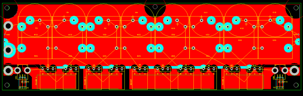
Notice that the power board is designed for 3 separate phases, with 2 IGBTs (to form a half bridge) per phase, plus 4 IGBTs for the boosting section. That way you could boost, say, 150 amps (shared between 2 IGBTs) at 150v up to 75amps at 300volts. Then the 300volt section would be happy with 1 IGBT, and the low voltage section would be happy with the 150amps shared between 2 IGBTs. Then, to minimize the stray inductance, the driver board mounts perpendicularly to the power board, and the IGBT legs get soldered directly to the driver board. So, the driver board is designed to fit exactly with the footprints of the to-247 IGBTs. The IGBTs get clamped against the base plate with the mounting hardware accessible, "south" of the power board. The legs get bent at a 90 degree angle, and go through the power board, stick through and get soldered to the driver board. It should work OK with 247C and 247D length legs.
Also, notice that the power board accepts either 16 film caps or 8 film caps and 8 electrolytic caps. Exclusive use of film caps would allow for switching at maybe 700v.
Also, notice that 2 of the current sensors are on the power board. There's a new type of current sensor that goes up to 100amp, and is only $8 each, and has a response time of like 1uS. So, 2 of the phases are monitored cheaply (and that's all you need). An external sensor would be needed for the boost section for hardware overcurrent protection. To keep things small, you have to solder the 6 gauge or whatever cable to the surface of phase 2, and to the boost section.
Doing it this way makes the size about 12.35" x 3.6" x 3.6" or so, so it's pretty small and not much wasted space. The down side is it's very much not flexible, but there is no wiring and twisting wires to the power section. The nice thing is, it's really cheap, about as cheap as I can make it.
I could have the 2 microcontrollers speak if I doubled up on the PGC and PGD, which means adding a switch after it is programmed. But then that means possibly changing the pins of the debugger (you have 3 choices for the 2 debugging pins). I could then do the throttle & brake & temperature & temperature2, & voltage on the dspic2010, but would have to send the data to the other one. That means adding voltage monitoring, which adds around $15 or so cost, which isn't bad. There's room on the control board.
The control board is going to be cheap to make, so I could make the other changes later too. I was just trying to do "good enough" for as cheap as possible, without too much extra complexity. I guess I started worrying about messing with PGC and PGD and debugging and sending the important things like throttle so that the dspic4011 then had 2 separate UART conversations going at the same time (uart1 and uart2).
Last edited by MPaulHolmes; 10-15-2015 at 06:17 AM..
|
|
|
|
|
The Following 2 Users Say Thank You to MPaulHolmes For This Useful Post:
|
|
|
10-15-2015, 12:41 AM
|
#2189 (permalink)
|
|
Master EcoModder
Join Date: Sep 2010
Location: Saskatoon, canada
Posts: 1,488
Thanks: 746
Thanked 565 Times in 447 Posts
|
Quote:
Originally Posted by MPaulHolmes
The control board is going to be cheap to make, so I could make the other changes later too. I was just trying to do "good enough" for as cheap as possible, without too much extra complexity. I guess I started worrying about messing with PGC and PGD and debugging and sending the important things like throttle so that the dspic4011 then had 2 separate UART conversations going at the same time (uart1 and uart2).
|
Sounds 'good enough' to me!
10 HP at 72V is .. 104A ..
Will it push more current for maybe 10s? Maybe 200A?
Just interested ... |
|
|
|
|
10-15-2015, 12:54 AM
|
#2190 (permalink)
|
|
PaulH
Join Date: Feb 2008
Location: Maricopa, AZ (sort of. Actually outside of town)
Posts: 3,832
Thanks: 1,362
Thanked 1,202 Times in 765 Posts
|
At 72v, there are 2 IGBTs available in parallel for the boosting. There are some very impressive IGBTs coming out:
IRGPS66160DPbF is evidently capable of 150amp at 50% duty cycle!!! It's in the SUPER 247 package.
IRGPS66160DPBF Infineon Technologies Americas Corp. | IRGPS66160DPBF-ND | DigiKey
There's plenty of room for the super 247 package, as there is 0.950 inch for each TO-247 (which means TO-264 can fit too).
So, the absolute maximum would be 300 amps in the boost section, but I think 200amp would be OK for short periods of time with the right monstrosity of an IGBT.
Last edited by MPaulHolmes; 10-15-2015 at 06:03 AM..
|
|
|
|
|
The Following 3 Users Say Thank You to MPaulHolmes For This Useful Post:
|
|
|


