Hey squiggles! You little Devil ('s advocate!) hehe. I am really really grateful for your analysis. You are right about the while loops. They have all been eliminated. Everything is done with interrupts now. We need to upload a newer version of the software to the wiki..
I'll pass along your suggestion about the layout possibly diminishing the isolation to the engineer that's doing the testing of the control section in the lab. Thank you for raising that concern!
timer1 is initialized in the function InitPWM();
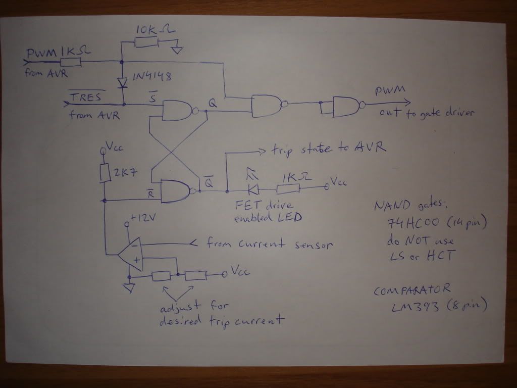
The NAND gate circuit is responsible for automatic overcurrent shutdown. It's a little tricky, but here it goes!
First, here's the overcurrent protection circuit, taken out of the main circuit:

I'm calling high signals 1 and low signals 0. This is the sequence of events -
I. IF CURRENT OVERFLOW SUDDENLY HAPPENS
1) R_BAR: 1 ---> 0
2) S_BAR: 1 ---> 1
3) Q: ??? ---> 0
4) Q_BAR: ??? ---> 1
5) PWM output to gate driver: ??? ---> 0
Because the TRIP_STATE (which is Q_BAR) is now 1, the microcontroller now knows that the mosfet driver has been disabled. I can re-enable the driver at my leisure.
II. IF YOU CLEAR S_BAR (TRIP_RESET)
1) S_BAR: 1 ---> 0
2) Q_BAR: 1 ---> 0
3) Q: 0 ---> 1
4) R_BAR: 1 // if R_BAR is back to 1, all is well, so let's pretend that.
5) PWM output to gate driver is still 0!
III. IF YOU THEN SET S_BAR (TRIP_RESET)
1) S_BAR: 0 ---> 1
2) R_BAR: 1 // LET'S PRETEND
3) PWM output to gate driver is now 1! Hurray, finally we have power!
///////////////////////////////////////////////////////////////////////////////////
Delay(uSecond) would be way better. I agree.
BY THE WAY, THE OVERCURRENT CIRCUIT HAS BEEN MODIFIED SINCE THE MOSFET DRIVER IS NOW THE INVERTING TYPE. That circuit above was for the original controller (version 1).