07-18-2009, 07:50 PM
|
#2031 (permalink)
|
|
PaulH
Join Date: Feb 2008
Location: Maricopa, AZ (sort of. Actually outside of town)
Posts: 3,832
Thanks: 1,362
Thanked 1,202 Times in 765 Posts
|
I don't know when people should do a group buy. There need to be at least a few simple changes to the control section before a group purchase.
PI loop results so far! It looks sort of similar to the previous graph, but check out the scale! This one doesn't overshoot, and gets there WAY faster! It takes about 0.005 seconds to make current match perfectly with throttle if you want the throttle to change from 0 to 50 (on a scale of 0 to 500). Each tick mark on the x-axis is 1/4000 of a second.
This would definitely NOT be granny mode. It should get you to 500 amps without overshoot (I think, there is no safe way to test it without destroying my motor) in 0.05 seconds. hehe. That's disturbing.
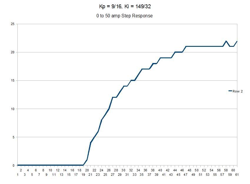
Ignore the y-axis scale. It's a long story. Basically it should say up to 50 amps where the graph levels off, but I didn't feel like changing it.
Last edited by MPaulHolmes; 07-18-2009 at 07:55 PM..
|
|
|

|
 Today Today
|
|
|
|
 Other popular topics in this forum...
|
|
|
|
|
07-19-2009, 03:41 AM
|
#2032 (permalink)
|
|
EcoModding Lurker
Join Date: Mar 2009
Location: Britol, UK
Posts: 11
Thanks: 0
Thanked 0 Times in 0 Posts
|
Paul,
We've got a whole load of interest here in Bristol, UK. Is anyone building a UK parts list? Perhaps we could do it?
Nikki.
|
|
|
|
|
07-19-2009, 07:20 AM
|
#2033 (permalink)
|
|
EcoModding Lurker
Join Date: Jun 2009
Location: Australia
Posts: 35
Thanks: 0
Thanked 3 Times in 3 Posts
|
Paul,
I just finished the PCB layout for the power board. Can you please have a look at it and tell me what you think? I am thinking it should be made in 4oz cu.
Mcudogs
|
|
|
|
|
07-19-2009, 08:00 PM
|
#2034 (permalink)
|
|
EcoModding Lurker
Join Date: Apr 2009
Location: Mauston, WI
Posts: 20
Thanks: 1
Thanked 8 Times in 7 Posts
|
Quote:
Originally Posted by MPaulHolmes

An interesting thing to consider for all those clutchless people in the house. If you do throttle proportional to current only, it can cause slight problems under certain circumstances.
For example, let's say you took the car out of gear, and you are coasting at maybe 25 mph. Now let's say you want to put it in gear before stopping. Well, you have to rev up the unloaded motor a bit to be able to put it in gear. However, throttle proportional to current means that an unloaded motor is VERY sensitive.
|
This seems like a problem even if you aren't in neutral. If I'm coming into town after driving on the highway, I think* I'm going to need to rev the motor to shift into a lower gear. This seems really necessary if I've put lighter or synthetic oil in the transmission. EV drivers: is this an issue?
Jack
* No experience driving a clutchless EV, just a Muncie crash box. |
|
|
|
|
07-19-2009, 09:27 PM
|
#2035 (permalink)
|
|
EcoModding Lurker
Join Date: Jul 2008
Location: Memphis, TN
Posts: 58
Thanks: 0
Thanked 1 Time in 1 Post
|
Paul that looks very good. What are your constants KP and KD?
Jay
|
|
|
|
|
07-19-2009, 10:07 PM
|
#2036 (permalink)
|
|
needs more cowbell
Join Date: Feb 2008
Location: ÿ
Posts: 5,038
Thanks: 158
Thanked 269 Times in 212 Posts
|
re: clutchless.
well, hmm, does measuring the motor voltage give you an indication of rpm? Or does it need an external sensor?
Do you want to ditch the current control stuff and have the throttle request an rpm, and the controller tries to comply within the current limit.
It would be a big step in a different direction at this point, for the sake of clutchless shifting and could be a can-o-worms. might want to wait for 2(3,4).0 for that. But if you add in a vehicle speed sensor , the controller can do the matching for you. And regen rears it's head as a mechanism for slowing down the motor when you lift up the pedal. But speed sensor also means you can track energy used/distance travelled type numbers. Again, probably not right now though, just thinking about maximizing that atmega 
__________________
WINDMILLS DO NOT WORK THAT WAY!!!
|
|
|
|
|
The Following User Says Thank You to dcb For This Useful Post:
|
|
|
07-19-2009, 10:26 PM
|
#2037 (permalink)
|
|
PaulH
Join Date: Feb 2008
Location: Maricopa, AZ (sort of. Actually outside of town)
Posts: 3,832
Thanks: 1,362
Thanked 1,202 Times in 765 Posts
|
I just got done trying different stuff for the throttle, since it has a bit of a thunk when taking off. I believe the thunk has to do with my coupler not being what it could be. Maybe my spider is getting worn out. or maybe there is some play somewhere else in the mechanical parts of the car. I can't wait for the others to tell me how the various throttles feel to them. I sort of regret the bucking bronco stuff that I did below now:
Hey Jay! Kd is 0, Kp is 9/16 and Ki is 149/32000. hehe. Sort of little, huh. I could make Ki larger but it was converging so nicely, and I just quit testing. I ran out of time. Also, the car started rocking back and forth pretty violently, so I thought I was going to ruin my coupler (the e-brake was on). I was testing a bunch of Ki's. I'd make a throttle step from 0 to 50, and then from 50 to 0, increment Ki a bit, watch on the laptop what was happening, and then close my eyes and pretend that I was on a bucking bronco!
Hey Nikki! I haven't heard of anyone doing a UK parts list. It was brought to my attention that at least 1 component wasn't RoHS compliant (had Pb in it), so we should change that. There are also a few minor changes needed on the control board, but I still need to start from scratch I think (I don't have the software that made it in the first place) and do the layout in expressPCB or another free one. Or anyone else want to change the layout? hehe. I've been sort of busy with school and getting the throttle perfect on my crappy $40 car, which may have mechanical problems that I'm trying to fix with stupid code! aaahh!
dcb: I DEFINITELY want to add an RPM sensor. It would make trivial a lot of difficuties I have had. I don't think the clutchless thing will be as much of a problem anymore, though, because I added some throttle ramping code. The PI loop is still super tight (current chases throttle better than a cougar chases it prey!), but now the throttle changes more gently. That seemed to take care of the shifting difficulties.
MCUDogs: It looks really beautiful! Comments: I think we can now get away with 4 holes for each of the 3 bus bars instead of 5 for 2 of them. I just used 5 before because the free bus bars I had already had holes at 1.5" increments, so I wanted to use those. 5 definitely doesn't hurt anything, though! It gives VERY good contact between the heat spreader and the heat sink. The holes between the capacitors should be perfectly in the center so as to be as far away as possible from the edges of the capacitors since the holes will be vias, and there needs to be room for soldering 10 gauge wire (which gets pushed into the holes).
Are those the actual dimensions for the TO-247 parts? It would be really nice not to have to bend the leads to fit them into those holes for the mosfets. It looks like you took care of that problem!
We could make the gate lead through-hole also. If we did that, then we would have to get rid of the tiny hole on the gate pad (which was for the gate resistor) and just solder the gate resistor to the other side. We would have to make the pad on the back side larger, and would have to move it so that the gate lead of the mosfet would go right through it. I think that would be an improvement (but a minor improvement). Thank you for all your hard work!
EDIT: MCUDOGS, I think those white borders around the 5/16" holes on the bottom side shouldn't be there.
EDIT AGAIN!: MCUDOGS, and if you really want to go crazy, on the bottom side if you move up the gate resistor pads, you could move up the B- 5/16" holes too, since B- bus bar gets attached at the bottom! That's one of the things I wanted to do different next time.
Last edited by MPaulHolmes; 07-19-2009 at 11:04 PM..
|
|
|
|
|
07-19-2009, 10:56 PM
|
#2038 (permalink)
|
|
AeroGuy
Join Date: Sep 2008
Location: Ohio
Posts: 224
Thanks: 73
Thanked 32 Times in 28 Posts
|
Hmmm, awesome progress being made. Might want to have 2 vehicles that you can test in parallel so you can fish out mechanical problems quicker. But I'm sure there are a lot of things we all wish for. Is it possible for you to still throw the controller on your bike?
|
|
|
|
|
07-19-2009, 10:59 PM
|
#2039 (permalink)
|
|
PaulH
Join Date: Feb 2008
Location: Maricopa, AZ (sort of. Actually outside of town)
Posts: 3,832
Thanks: 1,362
Thanked 1,202 Times in 765 Posts
|
Absolutely! It still works fine on the bike, but I would have to carry around a little 12v auxiliary battery to power it. it only uses like 2 watts or something so it could be a few AA batteries in series. hehe.
|
|
|
|
|
07-19-2009, 11:13 PM
|
#2040 (permalink)
|
|
EcoModding Lurker
Join Date: Jun 2009
Location: Australia
Posts: 35
Thanks: 0
Thanked 3 Times in 3 Posts
|
Paul,
Thanks for your comments! I will change the number of holes in the 4 hole bus bar to 5 if you like. All of the holes in the PCB will be through hole plated if there is copper on both sides of the board. So the vias between the caps will not need to linked and soldered.
Yes that is the right size for the TO-247 components and I agree that minumum bending is the way to go.
For the gate pad I will make it through hole and leave a bigger pad on the bottom side for this and the gate resistor. The gate resistor can also be mounted through hole as well to make it more secure.
The copper free boarders under the 5/16" holes are to isolate the top layer from the bottom layer, remember that all holes are through plated. If you don't do that you have to drill out the through hole plating and that would be messy.
|
|
|
|
|