Go Back   EcoModder Forum > EcoModding > Fossil Fuel Free > Open ReVolt: open source DC motor controller
Register Now
 Register Now
 

Reply  Post New Thread
 
Submit Tools LinkBack Thread Tools
Old 03-01-2011, 02:50 AM   #4421 (permalink)
EV Connoisseur
 
Join Date: Aug 2010
Location: Amsterdam
Posts: 309
Thanks: 70
Thanked 109 Times in 90 Posts
Hi,

The heatspreader alone is 1.5" so that is not gonna fit..

Check out the rtd explorer.. that will display all the values you want I guess.
RTD Explorer

  Reply With Quote
Alt Today
Popular topics

Other popular topics in this forum...

   
Old 03-01-2011, 07:36 AM   #4422 (permalink)
Master EcoModder
 
Join Date: Apr 2009
Location: Charlton MA, USA
Posts: 463

EVVette - '71 Chevy Corvette Coupe
Thanks: 31
Thanked 183 Times in 94 Posts
Quote:
Originally Posted by vwdevotee View Post
Hi, so I'm actually on page 75 of 112 now and had a couple of questions. Please forgive me if they've been answered, I'm still cruising and will reach them eventually. Anyway, I was just wondering if it would be possible to build a low profile version of the Cougar? I've got a purdy old amplifier that I was thinking of stealing the extruded aluminum case from. The whole unit could only be about 2 inches tall though to fit inside. My other questions are less aesthetically driven. Are there enough open I/O ports on the MCU to provide gauge feedback? Could a pulse signal be generated to mimic the tachometer pulse feed? What about controller temp sensor being used to drive the engine temp gauge in an instrument cluster? And the pack voltage to drive the fuel gauge in the cluster? Thanks in advance for all your input!
In order to fit the controller inside the amplifier case, you would have to basically redesign the power section from scratch. It would require a special design to fit circuit board and most likely caps that are larger in diameter and shorter in height. Its defiantly a possibility to do, but time consuming. I was working on going this route once, but stopped because of many factors.

As for tach output, The controller has the ability to output a pulse to run a tach with a little bit more hardware, but you first need to feed a tach signal into the controller to know the speed the motor is spinning. This also requires some hardware.

There currently code being worked on and tested to monitor and limit RPM based on one of the input pins on the ISP port that is not used after initial programming.

As for driving a temp gauge, This would just require some hardware and some code.

-Adam
__________________
www.EVVette.com - 1971 Corvette Coupe Conversion to all Electric!
www.AdamBrunette.com - Machining, CNC, Robotics and Electronics.

You can download RTD Explorer for the Cougar controllers at www.EVVette.com
  Reply With Quote
Old 03-01-2011, 04:09 PM   #4423 (permalink)
EcoModder
 
Join Date: Mar 2010
Location: New Zealand
Posts: 181
Thanks: 0
Thanked 33 Times in 20 Posts
Quote:
Originally Posted by DJBecker View Post
That's a different situation: the bolts are just providing the compression, rather than providing a conduction path.

I read the question as asking about the connection from the bus bar to the circuit board. The brass bolts are part of the conduction path.
I soldered my bus bars to the pcb and used steel bolts basically for mechanical strength ie so that stresses applied to the busbars wouldn't rip the Cu off the board. No prob!
__________________
Sometimes I sits and thinks and sometimes I just sits.
  Reply With Quote
Old 03-01-2011, 04:16 PM   #4424 (permalink)
EV Connoisseur
 
Join Date: Aug 2010
Location: Amsterdam
Posts: 309
Thanks: 70
Thanked 109 Times in 90 Posts
Hmm.. thats also an idea.. do you have a picture to share how that looks?
And does that mean you are not using the conductive epoxy?
  Reply With Quote
Old 03-01-2011, 04:37 PM   #4425 (permalink)
EcoModder
 
Join Date: Mar 2010
Location: New Zealand
Posts: 181
Thanks: 0
Thanked 33 Times in 20 Posts
Quote:
Originally Posted by flores View Post
Hmm.. thats also an idea.. do you have a picture to share how that looks?
And does that mean you are not using the conductive epoxy?
That's right, no conductive epoxy.
First you need to tin the pcb copper and I did that with a big, plumber's iron with a great fat tip about 1/2' across. Some paste flux and plumber's solder too. You can run the solder along the board quite neatly if you're careful. Then I heated the first busbar on the wok burner on our gas cooktop - wife was NOT home! You could use a propane torch, but mine was empty. Get it hot enough to tin as well. Again, paste flux and the big iron to control the solder flow. Once its nicely tinned, place the pcb on something flat and heat proof and find yourself a heavy weight that's also heat proof. Put a couple of bolts through the pcb holes to locate the bus bar. Get the busbar good and hot and stick it onto the board using the bolts to align it. Stick the big weight on to hold it all flat, stops the board warping. The heat should be enough to melt the tinning on the board ie the busbar acts like a big soldering iron. Once its cooled enough for the solder to solidify, check that its all flat and the busbar is in really close contact. If you've done it right a little bit of solder will have squished out around the edges. Not too much or you will have to file it off.
You will see from the photos that I built mine with all the busbars out one end. Did this so it would fit in the available space.

Note: To show the area to be tinned on the pcb, I put the busbars in place and ran along the edges with a pencil. That helps to keep the solder where it needs to be.
Attached Thumbnails
Click image for larger version

Name:	Power Bd 2.jpg
Views:	136
Size:	60.9 KB
ID:	7876   Click image for larger version

Name:	Power Bd 1.jpg
Views:	149
Size:	61.5 KB
ID:	7877  
__________________
Sometimes I sits and thinks and sometimes I just sits.

Last edited by harlequin2; 03-02-2011 at 03:55 PM.. Reason: correction
  Reply With Quote
The Following 2 Users Say Thank You to harlequin2 For This Useful Post:
flores (03-02-2011), MPaulHolmes (03-02-2011)
Old 03-02-2011, 02:03 AM   #4426 (permalink)
PaulH
 
MPaulHolmes's Avatar
 
Join Date: Feb 2008
Location: Maricopa, AZ (sort of. Actually outside of town)
Posts: 3,832

Michael's Electric Beetle - '71 Volkswagen Superbeetle 500000
Thanks: 1,368
Thanked 1,202 Times in 765 Posts
That's pretty, Harlequin2...

My Mill broke today! Well, the stupid motor starting capacitor shorted out. I opened the case, and flipped the switch, and it looked like some sort of faraday cage experiment:


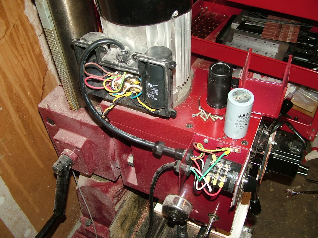
I ordered a new capacitor today and hopefully the other capacitor is still good. crap. I didn't think to check that one too. I'm an idiot.


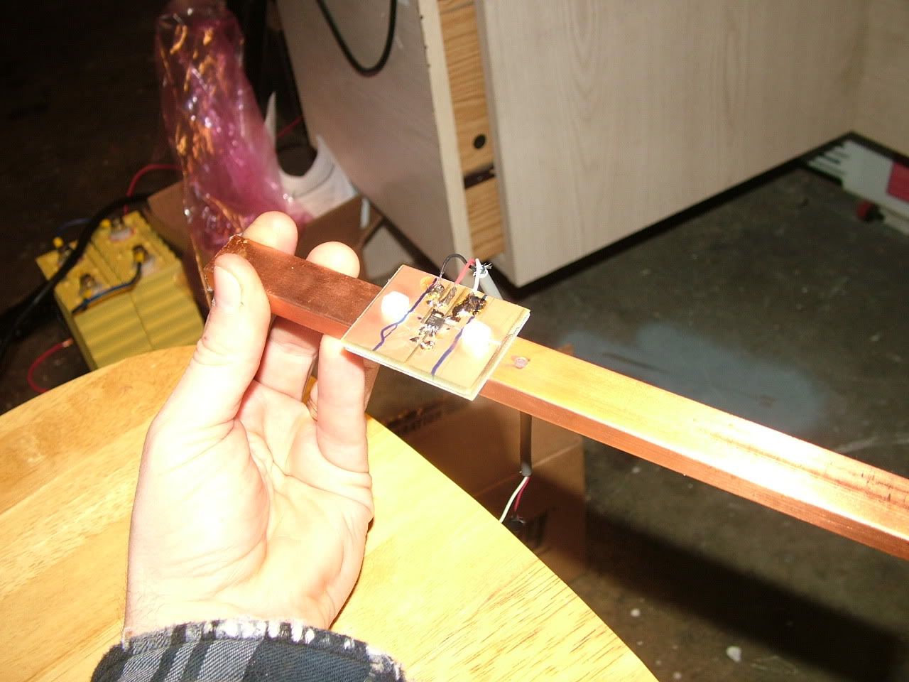
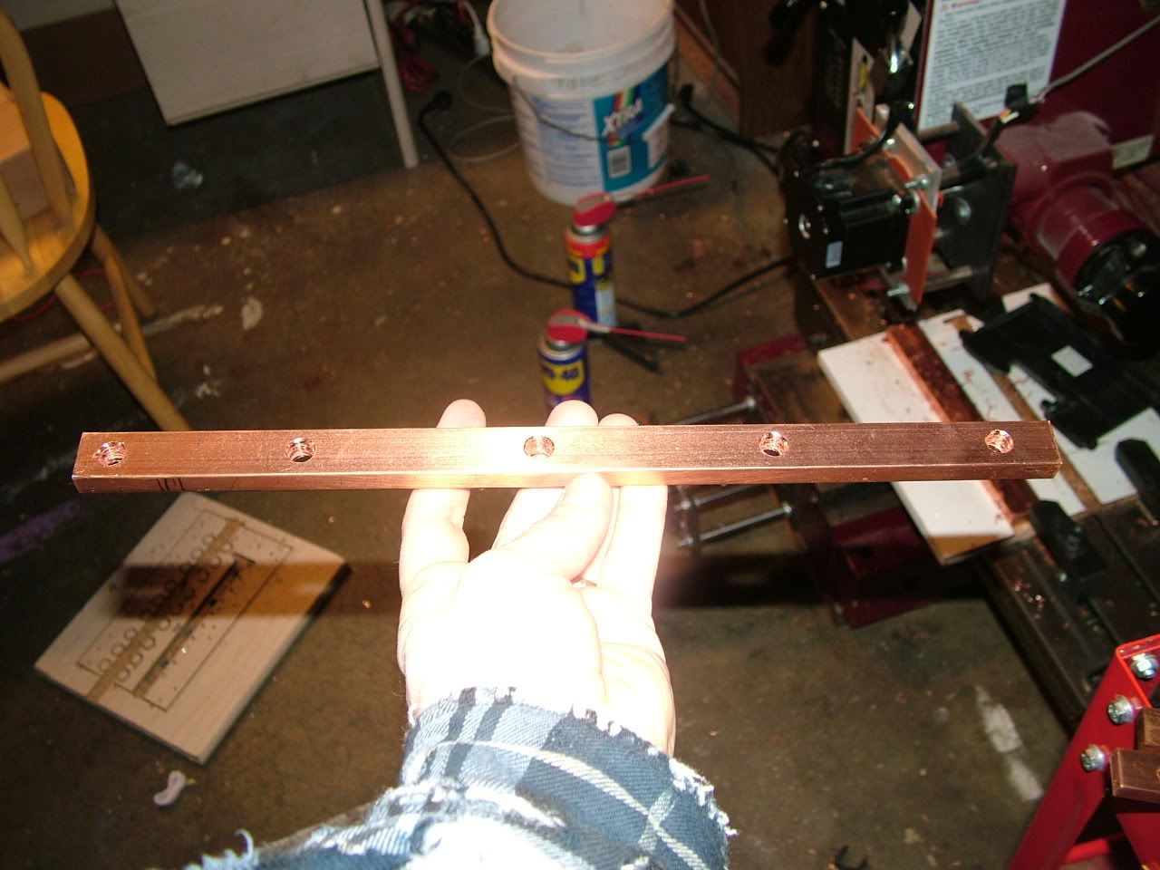
Since I couldn't do no milling today, gal dern it, I decided to finally test the melexis HB sensor. I drilled mounting holes in 1/4" x 3/4" bus bar, and also the big 1000amp controller 3/8" x 3/4" bus bar. Only had time to test on the 1000amp bus bar. Results were 1000 amps corresponds to an increase in voltage of 1.74v. The linear range is 2v, so it's well inside that. The spacing was 0.125" above the bus bar. I made a pcb that will be sent in soon, since the melexis HB requires capacitors that the low field version didn't require. This made it difficult to make on the mill:


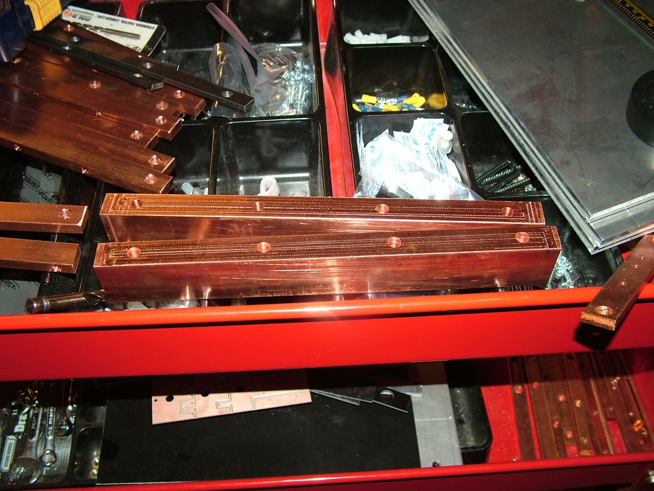
One of the 3 heat spreaders, with the 4 big holes drilled, and the top milled nice and flat:


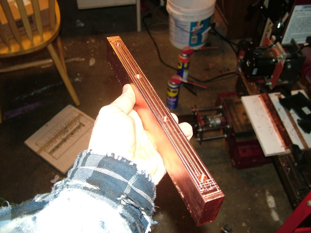
B+ and B- Bus bars. Notice that they will be mounted so the skinny side is in contact with the board. This should reduce the stray inductance, since it cut out around 3/8" from the top, and 3/8" from the bottom path length:
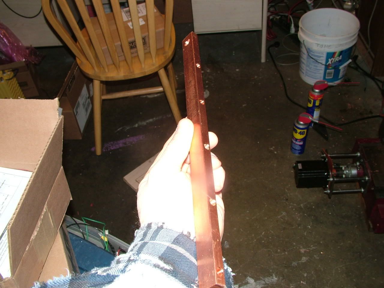

M- bus bar:


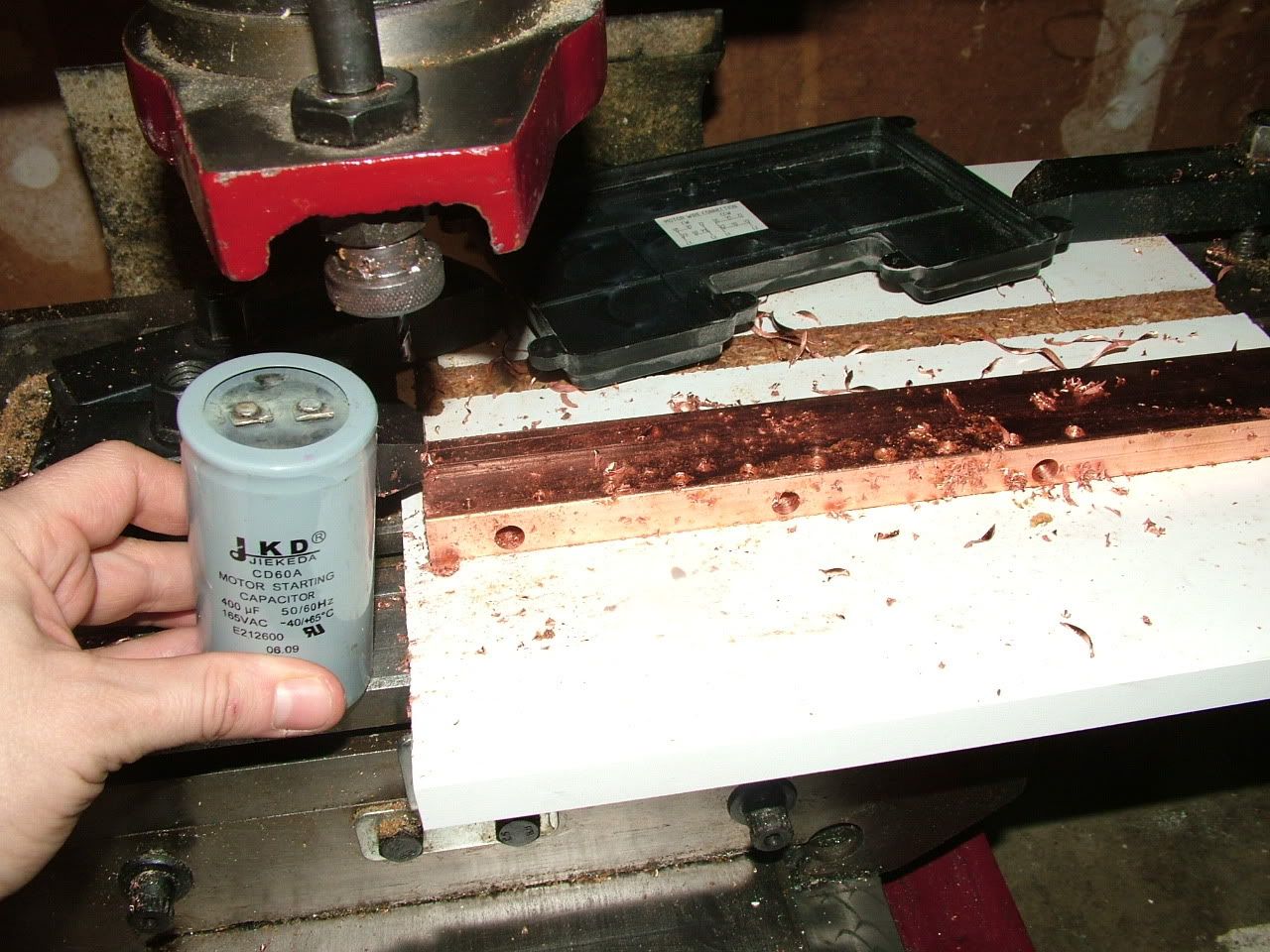
Right in the dang middle of the stupid drilling!!! The stupid motor start capacitor broke!:


The other 2 copper heat spreader bars:
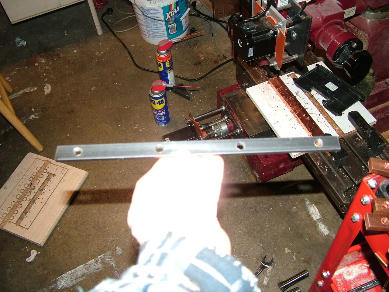

Steel bar:


Those boards should be here maybe in a couple more days! And um, I can't remember what else I was going to say. dang it.
__________________
kits and boards

Last edited by MPaulHolmes; 03-02-2011 at 03:37 PM.. Reason: they were dang heat spreader bars, not bus bars.
  Reply With Quote
Old 03-02-2011, 03:58 PM   #4427 (permalink)
EcoModder
 
Join Date: Mar 2010
Location: New Zealand
Posts: 181
Thanks: 0
Thanked 33 Times in 20 Posts
Just wondered what special precautions you need for drilling copper? I vaguely seem to recall that you should grind the drill to a different angle from that used for drilling steel. else it tends to dig in. And what about drill speed?
__________________
Sometimes I sits and thinks and sometimes I just sits.
  Reply With Quote
Old 03-02-2011, 05:43 PM   #4428 (permalink)
PaulH
 
MPaulHolmes's Avatar
 
Join Date: Feb 2008
Location: Maricopa, AZ (sort of. Actually outside of town)
Posts: 3,832

Michael's Electric Beetle - '71 Volkswagen Superbeetle 500000
Thanks: 1,368
Thanked 1,202 Times in 765 Posts
With copper, for 3/16" drill bits and bigger, I use about 450 rpm. Also, I spray it with wd40, and pause and pull up regularly to keep the bit cleaned off, so the copper doesn't weld to the tip.
__________________
kits and boards
  Reply With Quote
Old 03-02-2011, 07:02 PM   #4429 (permalink)
EcoModder
 
Join Date: Mar 2010
Location: New Zealand
Posts: 181
Thanks: 0
Thanked 33 Times in 20 Posts
OK, thanks for that.
__________________
Sometimes I sits and thinks and sometimes I just sits.
  Reply With Quote
Old 03-02-2011, 07:24 PM   #4430 (permalink)
EcoModding Apprentice
 
dave koller's Avatar
 
Join Date: Feb 2010
Location: Northern Wisconsin
Posts: 137
Thanks: 32
Thanked 39 Times in 23 Posts
I have a shirt like that !!! I call it my "fat" shirt! It is worn on the sleeve the same way -- LOL.....
Lurking............

__________________
Dave ...
  Reply With Quote
Reply  Post New Thread


Similar Threads
Thread Thread Starter Forum Replies Last Post
Paul and Sabrina's Cheap 3 Phase Inverter (AC Controller) with Field Oriented Control MPaulHolmes Fossil Fuel Free 3480 05-04-2022 05:43 PM
Paul & Sabrina's Cheap EV Conversion MPaulHolmes Fossil Fuel Free 542 11-12-2016 09:09 PM
Three Dirt Cheap DIY Electric Cars - Part 5 SVOboy EcoModder Blog Discussion 0 12-12-2008 04:10 PM


Powered by vBulletin® Version 3.8.11
Copyright ©2000 - 2024, vBulletin Solutions Inc.
Content Relevant URLs by vBSEO 3.5.2
All content copyright EcoModder.com