 06-27-2011, 12:14 AM
|
#4891 (permalink)
|
|
EcoModding Lurker
Join Date: Jun 2011
Location: Tennessee
Posts: 16
Thanks: 4
Thanked 1 Time in 1 Post
|
A couple years ago, I was trying to figure out how to make an igbt controller for a small ev conversion... I bought a 600a 1200v igbt, and the stuff for the bg1a board. Well life derailment, and a couple years, I can't wrap my head around any of it. I think it's better to sell off what I have and buy one of Paul's 500a kits. It meets my needs and and I'm a lot better at soldering than figuring out things these days  thanks for the help from the folks who were trying to lead me in the right direction.
Mike
|
|
|

|
 Today Today
|
|
|
|
 Other popular topics in this forum...
|
|
|
|
 06-27-2011, 12:15 PM
|
#4892 (permalink)
|
|
EcoModding Lurker
Join Date: Jun 2010
Location: Texas
Posts: 30
Thanks: 0
Thanked 1 Time in 1 Post
|
Troubleshooting.
Hi there, so i need some help troubleshooting the controller.
I finished building it, and plugged it into the car. Nothing.
Heres what i have so far,
The green and yellow LEDs are on and solid.
The RTD Explorer is reacting when i push the pedal, so something is happening.
The battery voltage is at 124v
The motor works coz i tested it independantly.
what should i start looking at in the controller?
please advise me, but remember i only have a digital multimeter to test with.
thank you much!
|
|
|

|
 06-27-2011, 12:27 PM
|
#4893 (permalink)
|
|
EV test pilot
Join Date: Jan 2008
Location: Oconomowoc, WI, USA
Posts: 4,435
Thanks: 17
Thanked 663 Times in 388 Posts
|
How about your main contactor or main disconnect?
Did you check those yet? I your main contactor closing after pre-charge? Is your main battery disconnect connected?
|
|
|

|
 06-27-2011, 01:03 PM
|
#4894 (permalink)
|
|
PaulH
Join Date: Feb 2008
Location: Maricopa, AZ (sort of. Actually outside of town)
Posts: 3,832
Thanks: 1,362
Thanked 1,202 Times in 765 Posts
|
Hi Voltmatic automation! I would first disconnect B+, B- and M- from the controller, so there is no high voltage there. And don't forget to discharge the capacitor bank. 120v in that bank can kill you. You definitely don't want to begin the debugging process with power hooked up. With the top off of the controller, measure voltage from any of the gate resistors to PH1 or PH2. First with zero throttle, and then with non-zero throttle (it doesn't have to be full throttle). The voltage should change from 0v to 12v. Check that first. If it stays at 0v, then there's a problem on the control board, and we'll keep backing up until we find the bad little culprit!
Last edited by MPaulHolmes; 06-27-2011 at 01:10 PM..
|
|
|

|
 06-28-2011, 09:35 PM
|
#4895 (permalink)
|
|
EcoModding Lurker
Join Date: Jun 2010
Location: Texas
Posts: 30
Thanks: 0
Thanked 1 Time in 1 Post
|
Troubleshooting Cont.
The throttle changed just like you said it would !
From 0 to 12v.
Whats next?
|
|
|

|
 06-28-2011, 10:03 PM
|
#4896 (permalink)
|
|
PaulH
Join Date: Feb 2008
Location: Maricopa, AZ (sort of. Actually outside of town)
Posts: 3,832
Thanks: 1,362
Thanked 1,202 Times in 765 Posts
|
sERIOUSLY?! But the power section isn't working? And you soldered mosfets along B- bar, and diodes along B+ bar?
Last edited by MPaulHolmes; 06-29-2011 at 10:18 AM..
|
|
|

|
 06-28-2011, 11:55 PM
|
#4897 (permalink)
|
|
EcoModding Lurker
Join Date: Jun 2010
Location: Texas
Posts: 30
Thanks: 0
Thanked 1 Time in 1 Post
|
Troubleshooting Cont.
Oh man, dont say that...all that solder work....gasp...
i will take a look tomorrow, heres hoping everything is in there right (and the problem is something else)
 |
|
|

|
 06-29-2011, 10:20 AM
|
#4898 (permalink)
|
|
PaulH
Join Date: Feb 2008
Location: Maricopa, AZ (sort of. Actually outside of town)
Posts: 3,832
Thanks: 1,362
Thanked 1,202 Times in 765 Posts
|
Also, verify that from M- to B-, you have very large resistance, and when you precharge the caps, that it stays precharged. So there's not much leaking from B+ to B-. and that you have PH1 and PH2 soldered into place. And that you have all 10 gate resistors soldered in too. The MOSFETs have thicker legs, so yo can just see if the legs closest to the B- bar are thicker than the ones closest to the B+ bar.
|
|
|

|
 07-01-2011, 11:56 AM
|
#4899 (permalink)
|
|
Master EcoModder
Join Date: Sep 2009
Location: Ireland
Posts: 734
Thanks: 26
Thanked 304 Times in 171 Posts
|
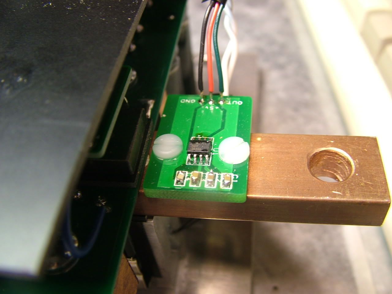
Hey Paul how did you mount the melexis current sensor board on the busbar?
__________________
Now, Cole, when you shift the gear and that little needle on the ammeter goes into the red and reads 2000 Amps, that's bad.
www.evbmw.com
|
|
|

|
 07-01-2011, 12:07 PM
|
#4900 (permalink)
|
|
PaulH
Join Date: Feb 2008
Location: Maricopa, AZ (sort of. Actually outside of town)
Posts: 3,832
Thanks: 1,362
Thanked 1,202 Times in 765 Posts
|
BAM!

|
|
|

|
|
The Following 2 Users Say Thank You to MPaulHolmes For This Useful Post:
|
|
|