Go Back   EcoModder Forum > EcoModding > Fossil Fuel Free
Register Now
 Register Now
 

Reply  Post New Thread
 
Submit Tools LinkBack Thread Tools
Old 07-22-2009, 01:27 AM   #11 (permalink)
Joe
 
Join Date: Feb 2009
Location: phx
Posts: 260
Thanks: 0
Thanked 48 Times in 38 Posts
I loaded the new code that had the pi loop and it worked a lot better. The ramp rate might be a little slow, but I'm more interested in the new 'power' code. Paul, you'll have to send that when you get a chance.

I think my temp probe thing is about ten degrees too high. That's at ambient temp though, not sure about higher temps. I think one easy test would be to put it in boiling water too see what I get. Nevertheless, I cruised around the block tonight and watched the guage. Temps on themosfet and diode got to around 100C at some points, but that's what my guage read, so I'm not sure that it's really that high. I think the guage I have inthe heatsink is pretty accurate (I bought it online) and it reads the temp at the base of the controller. This reading changed quite a bit with throttle, but seemed to hover in the high 40s. On, it was actually kinda cool out tonight, 32 C.

If these numbers are right, we may need to look into better cooling or reducing heat. I read on the zeva site about ians design and how he's down to 5 ohm gate resistors. Paul, I think you mentioned some options to reduce heat...

__________________
ReVolt AZ testing thread:

http://ecomodder.com/forum/showthrea...ting-9325.html
  Reply With Quote
Alt Today
Popular topics

Other popular topics in this forum...

   
Old 07-22-2009, 01:40 AM   #12 (permalink)
Joe
 
Join Date: Feb 2009
Location: phx
Posts: 260
Thanks: 0
Thanked 48 Times in 38 Posts
hm, was just thinking that brief excursions to high temperatures might be ok. i guess as long as the components stays below some maximum temp and nominally stay rather cool (like below 80C?) they oughta last pretty long. I noticed that after accelerating the temps would be high, but they'd drop in minute or so...

i need to verify my measurement system and do some more testing...
__________________
ReVolt AZ testing thread:

http://ecomodder.com/forum/showthrea...ting-9325.html
  Reply With Quote
Old 07-22-2009, 01:52 AM   #13 (permalink)
Joe
 
Join Date: Feb 2009
Location: phx
Posts: 260
Thanks: 0
Thanked 48 Times in 38 Posts
man, keep forgetting things. also, i noticed that the minimum amps I can send to the motor is 80 amps. any idea why this is? do you notice this too?

On my charger, i noticed that the optoisolator has some lag when the voltage is rising, almost like it has some internal capacitance. Thus, there was a minimum duty cycle that would actually get through to the gate driver.

do you have this problem too? or maybe it's something in software with the minimum throttlepos maybe?
__________________
ReVolt AZ testing thread:

http://ecomodder.com/forum/showthrea...ting-9325.html
  Reply With Quote
Old 07-22-2009, 03:24 AM   #14 (permalink)
PaulH
 
MPaulHolmes's Avatar
 
Join Date: Feb 2008
Location: Maricopa, AZ (sort of. Actually outside of town)
Posts: 3,832

Michael's Electric Beetle - '71 Volkswagen Superbeetle 500000
Thanks: 1,368
Thanked 1,202 Times in 765 Posts
There are several things for future versions, like multiple gate drivers to allow for smaller gate resistors. Another thing that would help is if I would have torqued the stupid mosfets'/diodes' clamps all the way down. I'm such an idiot!!! If you ever want to do that, you will have to unsolder each gate resistor from the control board, unsolder the 2 thicker power ground wires from teh control board, and then remove the control board, unbolt the 5 bolts, flip it over, take off the base plate, tighten the clamps, and then re-assemble. I'm sorry about that. Maybe they are OK though.

Syncronous rectification is another option. Another option is to have 2 separate heat spreaders. One for the diodes and one for the mosfets. Clamp teh mosfets' back DIRECTLY to the heat spreader, which makes the heat spreader wired to M-. The heat spreader then would have to be isolated from the base plate. Similarly do the same with the diodes. Must go to bed! haha!

That's really serious about the 80 amp minimum. Maybe I messed up so that the dead zone does nothing, but then the throttle goes from 0% to around 12-13%? I really need to look at the code to see if that is true. I don't have a motor amps measuring thing. I can sort of measure battery amps, though, and I have never noticed that. hmm! I'll check tomorrow.
__________________
kits and boards
  Reply With Quote
Old 07-22-2009, 02:22 PM   #15 (permalink)
Joe
 
Join Date: Feb 2009
Location: phx
Posts: 260
Thanks: 0
Thanked 48 Times in 38 Posts
Quote:
Originally Posted by MPaulHolmes View Post
There are several things for future versions, like multiple gate drivers to allow for smaller gate resistors. Another thing that would help is if I would have torqued the stupid mosfets'/diodes' clamps all the way down. I'm such an idiot!!! If you ever want to do that, you will have to unsolder each gate resistor from the control board, unsolder the 2 thicker power ground wires from teh control board, and then remove the control board, unbolt the 5 bolts, flip it over, take off the base plate, tighten the clamps, and then re-assemble. I'm sorry about that. Maybe they are OK though.
That does seem like quite a process to get in there! more pressure would probably help. I didn't see the thermal pad material on the BOM - do you know what it is or what the specs are?

I ran the numbers for smaller gate resistors for various design points: The first is the original 30 ohm, the 2nd is 15 ohm, and the last is 5 ohm. On paper at least, it shows up to ~50% less heat with the 5 Ohm.


Quote:
Syncronous rectification is another option. Another option is to have 2 separate heat spreaders. One for the diodes and one for the mosfets. Clamp teh mosfets' back DIRECTLY to the heat spreader, which makes the heat spreader wired to M-. The heat spreader then would have to be isolated from the base plate. Similarly do the same with the diodes. Must go to bed! haha!

I'm skeptical of synchronous rectification. I think it makes sense if the diode is on for a large portion of the duty cycle, but in our case, we're often above a duty cycle of 0.5. From the chart, the Wdiode is often less than the sum of the Wfet (due to Rds) and Wswitching (indicating that adding another set of mosfets would actually increase losses). Even for the 5 ohm case, there's only a significant advantage at low speeds.

I think sync rectification is most useful for low voltage power supplies that convert 120V down to 12 or something. In that case, the duty cycle is so low that the mosfet is only briefly on and the diode is on a long time, and thus, is the source of a lot of heat.

I do like the idea of eliminating the thermal pad... seems like it creates other problems, huh...

Quote:
That's really serious about the 80 amp minimum. Maybe I messed up so that the dead zone does nothing, but then the throttle goes from 0% to around 12-13%? I really need to look at the code to see if that is true. I don't have a motor amps measuring thing. I can sort of measure battery amps, though, and I have never noticed that. hmm! I'll check tomorrow.

I felt that the minimum throttle is very noticable. like, cruising at 25mph, i'd back slowly off the throttle, i could feel the torque dropping, and then bam - instantly zero. For me, it's at 80amps, but maybe it's less at 72v and a 6.7" motor.
__________________
ReVolt AZ testing thread:

http://ecomodder.com/forum/showthrea...ting-9325.html
  Reply With Quote
Old 07-23-2009, 03:33 PM   #16 (permalink)
Joe
 
Join Date: Feb 2009
Location: phx
Posts: 260
Thanks: 0
Thanked 48 Times in 38 Posts
Ran into a new problem that I think is purely software.

First, some background. I have my battery volt meter across the controller battery inputs, B+ and B-. Thus, I'm essentially reading the voltage at the controller. This is nice because I can watch the voltage on the caps rise as they precharge, but that's really about it.

Also, I have my contactor wired to the throttle pot switch. I set it up so that the contactor is open when my foot's off the pedal, but closes once it's depressed. It seems that most people have the contactor close for the trip duration, but I like the reassurance that the battery gets disconnected when I step off the pedal. If something goes wrong, my first instinct - to get off the gas - will be a first line of defense in breaking the circuit. The precharge resistor keeps the caps charged when I'm off the throttle.

SO - the issue. I noticed my voltage drop to zero and then rise slowly again like the caps were precharging. This happens when I take my foot off of the throttle too fast.

What's happening, I'm pretty sure, is due to the throttle ramp rate. I take my foot of the pedal, the contactor opens, but the PWM signal hasn't yet gone to zero. So, the controller is still sending power to the motor, but the battery is no longer connected, and the caps get drained to zero.

I'm pretty sure increasing the ramp rate (at least the ramp down rate) will solve this, so it's an easy fix, but a problem I definitely didn't foresee!


I posted this in the other forum...

Testing temperature update!

My probe thing is whacked!

I brought out the rice cooker filled with water and put in a temp probe from my handy clamp meter and the 4th unused probe from my hacked together POS, turned it on and recorded the two values as the water temp rose.

at an actual temp of 58C, my probe read 102C
at an actual temp of 75C, my probe read 152C

I knew it was a little off at lower temperatures, but it's way off at higher temps!

So, firstly, if the top of the mosfet cases are only ~60C, and maybe it's a bit warmer at the junction, that might be ok. It was only a 4 mile trip around the block, so we'll have to see what happens on longer runs or harder accelerations.

secondly, i'd like to fix my frickin code! I didn't necessarily plan my circuit too well and ended up with quite a ridiculous ADC to Temp curve that's 3rd order. Straight from excel, I was using this:

tempfine=0.00000041*(ADC^3) - 0.00055497*(ADC^2) + 0.35803595*ADC - 6.14221231;

where tempfine was initialized as float. I'll admit that I really don't know how this works for microcontrollers - I initially coded it up and loaded it, saw a value that was roughly room temperature, then squeezed a probe in my hand and saw another number that was roughly body temp and concluded it was good! Obviously it isn't!

Any ideas?
__________________
ReVolt AZ testing thread:

http://ecomodder.com/forum/showthrea...ting-9325.html
  Reply With Quote
Old 07-23-2009, 03:52 PM   #17 (permalink)
PaulH
 
MPaulHolmes's Avatar
 
Join Date: Feb 2008
Location: Maricopa, AZ (sort of. Actually outside of town)
Posts: 3,832

Michael's Electric Beetle - '71 Volkswagen Superbeetle 500000
Thanks: 1,368
Thanked 1,202 Times in 765 Posts
good diagnosis. That's exactly what's happening, Joe. If you are using the PI version with the slow ramp rate, to increase the ramp rate, there's a constant called THROTTLE_RAMP_RATE (I think it's called that). I think right now it's set to 4 maybe. Try changing it to 8 or 10 or something and see if that helps.
__________________
kits and boards
  Reply With Quote
Old 08-04-2009, 10:43 AM   #18 (permalink)
Master EcoModder
 
Join Date: Nov 2008
Location: Massachusetts, USA
Posts: 442
Thanks: 1
Thanked 60 Times in 45 Posts
How is the testing going and how many miles do you now have on the controller?
__________________
Civic EV http://2001-civic-ev.blogspot.com/
Solectria Force http://solectriaforce.blogspot.com/
  Reply With Quote
Old 08-04-2009, 11:43 AM   #19 (permalink)
Joe
 
Join Date: Feb 2009
Location: phx
Posts: 260
Thanks: 0
Thanked 48 Times in 38 Posts
Quote:
Originally Posted by TheSGC View Post
How is the testing going and how many miles do you now have on the controller?
good! I've been driving to work for the past 2 weeks in addition to whatever little errands I had to run. All in all, a little over 200 mi so far. Once the latch up thing was fixed and the throttle response was set, I've had no problems. The hardware overcurrent protection has saved our butts a few times, but now that the PI loop is working, it doesn't trip.

I think anything that would have failed in an infant mortality kind of way should have failed by now. Now it's just longevity - will it last 1000 miles or 100,000? We just gotta run it and find out.


I also have this post on the other page:

Paul suggested we investigate the sources of heat generation in the controller by changing the switching frequency in half. The result should reduce the switching losses by half at the expense of an audible whine and higher ripple current (I think?). It'll be easy to implement as well - just change the micro frequency to 8mhz using the internal oscillator.

The effect on temperatures, however, should be less than half - that is, the temps should be slightly more than half of what they were before due to the other sources of heat (diodes, Rds_on) that aren't changing.

Anyway, this would give us an idea about what to expect from reducing the gate resistance to speed up switch-on/off times, if we decide to pursue that.

Some observations:

1 - The ~8khz whine is not very loud, but it is very high pitch and I found it quite annoying. I don't think I could take it if I had to leave it like that.

2 - I increased Kp in the PI loop to account for the slower processor, but I forgot about the ramp rate. It took what seemed like forever to ramp up in current.

3 - I froze the micro once. Stepped on the pedal too hard - not sure why it locked up, but it did. It was very reliable at 16Mhz, so not sure why it would change - maybe something to do with the overcurrent reset or the response of the PI loop at the slower processing speed? I plan to change it back to 16 Mhz, so I'm not going to worry.

4 - As expected, the 'feel' of the controller didn't change (aside from the slow ramp).

5 - Temperatures. Conveniently, the ambient temp was about the same as in the video a few pages back - 42C. The only difference was that the sun was going down tonight while the video was in the sun, but since nothing is exposed, I think only the ambient temperature matters. I went on the highway pulling the same amps until the temps stabilized. Mosfet and diode were around 61, capacitor was at 65 (had just clicked up to 65 when I got to my exit - might've gone higher?). The heatsink probe was reading 52. If you happened to watch the part of the previous video where the camera is right in from of the probe display, you might remember the mosfet reading 67, diode 63, the capacitor a little lower than that (at that point), and the heatsink probe at 56C.

*Remember, these are just probes that are touching the case of the mosfets/diodes to get a ballpark temp reading.

So, Before at 15khz:
Mosfet - 67
Diode - 63
Cap - 60ish
Heatsink - 56

Now:
Mosfet - 61
Diode - 61
Cap - 65
Heatsink - 51

6 - The switching components ran cooler, but the caps did not. Previously, I had never seen the caps rise higher than the mosfets/diodes. Now, I suspect with the lower frequency and higher ripple current, the caps are generating more heat and are rising in temp.

7 - Previously, the mosfet ran hotter than the diode, but at half frequency, they were roughly the same temperature. Physically, they are fairly well thermally coupled due to the copper heat spreader, so I'd think a close temp is to be expected. The difference in temps before is likely due to the extra switching heat that is now cut in half. When the mosfets were generating a lot of heat before (more than the diode), they ran hotter.

8 - It's always interesting to compare the mathematical models to real measurements. Using the models for a mosfet and diode presented quite a few pages ago, the heat generation at 15 khz, half duty cycle, and 200 motor amps is 449W. Cutting the frequency in half reduces this to 273W, or a 39% decrease. If we assume that the thermal resistance stays the same, we can then say the component temperature-above-ambient should decrease by 39% as well. This hypothetically would give:

Mosfet - 57
Heatsink - 51
diode - should stay the same? It's producing the same heat as before, so...

However, this is not what was measured - the predictions are too low. The actual temperature changes are closer to a 26% decrease in temp, significantly less than the 40% prediction. Of course, there are so many assumptions that go into the model (which itself is just an approximation), so maybe these results are actually pretty good.

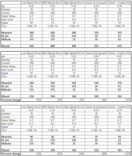
So, here are some other model heat gen results to chew on:

15 Ohm Rgate - 37% less heat generation
10 Ohm Rgate - 50% less heat generation
5 Ohm Rgate - 64% less heat generation

__________________
ReVolt AZ testing thread:

http://ecomodder.com/forum/showthrea...ting-9325.html
  Reply With Quote
Reply  Post New Thread


Similar Threads
Thread Thread Starter Forum Replies Last Post
Longtime Lurker Looking for Miles ZX40 Electric Micro van mods & information rmay635703 Fossil Fuel Free 49 07-06-2014 10:27 PM
Any interest in developing an open source fuel economy gauge/computer? MetroMPG OpenGauge / MPGuino FE computer 182 06-25-2010 07:00 AM
New guy interested in the Open Source motor controller rollins Introductions 3 03-09-2010 09:10 AM
can you use a DC motor controller to charge car battery from a higher voltage battery modmonster EcoModding Central 9 02-13-2009 07:14 PM
Open Source LEV Controller FrankG Alternative Transportation 1 03-24-2008 03:10 AM


Powered by vBulletin® Version 3.8.11
Copyright ©2000 - 2024, vBulletin Solutions Inc.
Content Relevant URLs by vBSEO 3.5.2
All content copyright EcoModder.com