06-04-2008, 06:21 PM
|
#191 (permalink)
|
|
MP$
Join Date: Jan 2008
Location: SW Ohio
Posts: 595
Thanks: 5
Thanked 19 Times in 14 Posts
|
 real world injector flow rate
With a reaction time of 1 millisecond for a typical injector before it is fully open, i would not be concerned with what fuel injectors are in my engine. Start with a generic number for cal., and drive it to calibrate.
Two injectors in the same engine will not even deliver the same amount of fuel. So the the cal. is going to be the average of all the injectors.
If you want to get get an approximate number without driving, let a warm engine idle for 6 minutes, and record the pulse numbers. times 10 gives pulses per hour.
Some where around 30 to 50 times (your mileage may vary) the idle for 6 min. number will be approx. pulses for 60 mph for one hour.
Most VSS sensors are on the transmission.
Anti-lock brake signal would prob. work also.(insert disclaimer here)
Last edited by diesel_john; 06-16-2008 at 10:37 AM..
|
|
|

|
 Today Today
|
|
|
|
 Other popular topics in this forum...
|
|
|
|
|
06-04-2008, 09:13 PM
|
#192 (permalink)
|
|
EcoModding Lurker
Join Date: Jun 2008
Location: ohio
Posts: 41
Thanks: 1
Thanked 0 Times in 0 Posts
|
I was just reading through your thread and think its amazing that all of you have the ability to perform such complex work. I am currently trying to decide what to go to college for and was wondering what type of degree some of you have and what you would call your line of work? Also, is it possible to just hook this to your OBD II port such as in this website. http://www.obddiag.net/projects.html
I think fuel injector pulse information comes through the OBD. Isnt that how the scan gauge works? |
|
|
|
|
06-04-2008, 10:05 PM
|
#193 (permalink)
|
|
EcoModding Apprentice
Join Date: Apr 2008
Location: Marietta, GA
Posts: 139
Scoob - '05 Subaru Impreza Outback Sport SE 90 day: 25.28 mpg (US)
Thanks: 0
Thanked 0 Times in 0 Posts
|
Well, I've got a degree in computer engineering (CpE), which is basically half electrical engineering (EE) and half computer science. I've worked as a hardware engineer, and now am a software engineer. I'm currently doing software support (which sucks), but it was a foot in the door w/ IBM, so I don't complain too loudly.  However, since I've been out of the down and dirty tech stuff, I'm a little out of practice, but at least I still know the language.
If this type of stuff excites you I definitely recommend looking into EE or CpE. Comp Sci is all software and you'll never get to tinker with that. EE is very heavy in math, so be prepared for it, as in be able to ace Calculus I, because you'll use it in every class afterwards. Math is the language of engineering.
And re: your question about OBD - yes, you could do this via the OBD port, but it would require a lot more interfacing circuitry (like the obddiag board), and wouldn't work on pre '96 cars that didn't have OBD-II. The primary purpose for this project is to cater to those pre '96 cars. One of the bonus side effects of this is the fact that it's cheap and easy to implement.
And back on a related note, I received my 'duino so I'll probably piece it (or some of it) together tonight. 
At dcb: Still haven't had the time to look up those ECU pinouts, but I have the service manual and entire wiring diagram for most Subaru Impreza years and some Legacy years, so I know I have it. If anyone needs a .pdf, lemme know.
I am still interested to figure out what I need to know about my injectors... 
Last edited by cmags; 06-04-2008 at 10:13 PM..
|
|
|
|
|
06-04-2008, 10:32 PM
|
#194 (permalink)
|
|
MP$
Join Date: Jan 2008
Location: SW Ohio
Posts: 595
Thanks: 5
Thanked 19 Times in 14 Posts
|
Quote:
Originally Posted by tom43571

I was just reading through your thread and think its amazing that all of you have the ability to perform such complex work. I am currently trying to decide what to go to college for and was wondering what type of degree some of you have and what you would call your line of work? Also, is it possible to just hook this to your OBD II port such as in this website. http://www.obddiag.net/projects.html
I think fuel injector pulse information comes through the OBD. Isnt that how the scan gauge works? |
Welcome Tom, the consensus is that Scanguage can't display pulse width. And maybe doesn't even use it.
To find the injector signal on your injector, you can use a dwell meter if you do not have a frequency scale on your DVM.
Last edited by diesel_john; 06-07-2008 at 01:55 PM..
|
|
|
|
|
06-04-2008, 10:35 PM
|
#195 (permalink)
|
|
Awesomeness personified
Join Date: Dec 2007
Location: Columbia, MO
Posts: 642
Thanks: 0
Thanked 28 Times in 18 Posts
|
Just a quick photo of my MPGuino.
I used a phone-jack to connect up all the wires so it's a bit tidier.
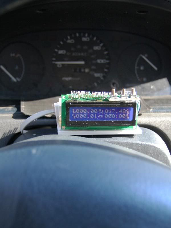
Still working on calibration. Mileage is showing up as about 80% of what it should be, and I guess fuel is being underreported by the same amount, if not a little more. The MPG numbers seem about 10-15% high, so we'll see.
__________________
"I got 350 heads on a 305 engine. I get 10 miles to the gallon. I ain't got no good intentions." - The Drive By Truckers.

|
|
|
|
|
06-04-2008, 10:41 PM
|
#196 (permalink)
|
|
EcoModding Lurker
Join Date: Jun 2008
Location: NC
Posts: 30
Thanks: 0
Thanked 0 Times in 0 Posts
|
Quote:
Originally Posted by diesel_john
Aren't most VSS sensors on the transmission.
|
The VSS on the civic is bolted to the top of the transmission. I've used that hole to fill the transmission when replacing the fluid as it is vertical and easy to reach from the top.  |
|
|
|
|
06-04-2008, 10:58 PM
|
#197 (permalink)
|
|
EcoModding Lurker
Join Date: Jun 2008
Location: Portugal
Posts: 8
Thanks: 0
Thanked 0 Times in 0 Posts
|
Hello there,
Very nice project you have there! I have a special interest in this project because... I've been working a similar project with a friend in the past few months. This thread already very long and I don't have the time now to go thoroughly all of the posts, but would like to make some comments and show what I have.
I would like to start by doing 2 comments:
1) The power feeding on your circuit should have some protection against voltage transients, and at least a fuse. Voltage transients are quite common in cars and may end-up killing, instantly or by a slow degrade then death, your arduino. Sometimes, it's enough to turn off the air conditioned to cause a good transient.
2) The amount of fuel that goes into the cylinder is not proportional only to injector opening time. At least in some fuel injected cars (I don't have the knowledge to speak for all), the fuel pressure on the "injector rail" depends on the trottle position; there's a regulating valve which will regulate the pressure depending on the pressure at the air input (controlled by the trottle). In our project we're planning to take both things into consideration.
The stage I'm currently at is that I've built the core of the prototype hardware (based on a ATmega88) and I'm coding the basic software to read the sensors. Since I was going to pull some wires on the car anyways, I decided to bring more signals into the device, and add it more features, like displaying 2 air temperature sensors, a clock (the LCD will replace the current car clock), lambda sensor, extra kms (miles) counters, speed warnings and other things I'm still thinking about. It will be able to connect to a PC through a serial port and log data. Below you can see the schematics and a pic of the current prototype (still just a board, but it's heart already beats  ). It's not the most updated schematics but that's the one I currently have on imageshack, I'll try to load a new one later.
Keep up with the good work, I hope we can exchange some knowledge.
Cheers!


Last edited by Njay; 06-04-2008 at 11:04 PM..
|
|
|
|
|
06-04-2008, 11:02 PM
|
#198 (permalink)
|
|
EcoModding Lurker
Join Date: May 2008
Location: USA
Posts: 59
Thanks: 0
Thanked 0 Times in 0 Posts
|
Quote:
Originally Posted by tom43571
I think fuel injector pulse information comes through the OBD. Isnt that how the scan gauge works?
|
I think OBD does not carry fuel injector info. Or it does, but only for some makers. I believe injector info is not part of the general OBD standard. OBD was designed about twenty years ago, and the primary impetus was smog control. That's what was on the mind of its designers, not helping drivers who were suddenly very motivated to deal with $4 gas.
Because it relies on OBD2, I think SG does not attempt to look at injector info. I think the Scangauge reports MPG via an estimation process, based on various indirect parameters, like airflow data. For certain cars under certain conditions, this can lead to problems with accuracy. Certain owners have noticed and reported accuracy problems. Aside from them, I have a feeling that a certain number of other owners are dealing with inaccurate data and simply don't realize it. I think certain kinds of errors probably have a tendency to balance out over the course of a fill. Therefore they will escape notice under the normal calibration procedure.
There are obviously many pros and cons when comparing SG and MPGuino. They are quite different. But the latter measures fuel flow in a more direct manner, and I think therefore has the potential to be more accurate, especially under certain conditions that seem to create problems for the SG. Maybe much more accurate. In this application, I think accuracy matters, and I think this is potentially a major advantage for the MPGuino.
But it's probably too soon to say for sure, and there will perhaps be similar issues with regard to errors that are not picked up by an ordinary calibration procedure.
I have enormous respect and admiration for the folks who are working on this. If the aggregate effort was expressed in dollars, it would be a big number. |
|
|
|
|
06-04-2008, 11:46 PM
|
#199 (permalink)
|
|
EcoModding Lurker
Join Date: May 2008
Location: USA
Posts: 59
Thanks: 0
Thanked 0 Times in 0 Posts
|
Quote:
Originally Posted by Njay
The amount of fuel that goes into the cylinder is not proportional only to injector opening time. At least in some fuel injected cars (I don't have the knowledge to speak for all), the fuel pressure on the "injector rail" depends on the trottle position; there's a regulating valve which will regulate the pressure depending on the pressure at the air input (controlled by the trottle).
|
Your project looks very interesting.
On the systems that I know about, the fuel pressure regulator maintains a constant pressure. But I'm definitely no expert, and I'd like to understand this better. What car has a system that works the way you described? |
|
|
|
|
06-05-2008, 12:11 AM
|
#200 (permalink)
|
|
needs more cowbell
Join Date: Feb 2008
Location: ÿ
Posts: 5,038
Thanks: 158
Thanked 269 Times in 212 Posts
|
Well I think the 95-98 saturns are afflicted. dieselJohns truck might be, but he put a check valve in the vacuum system and is counting on the 02 sensor to correct maybe? Maybe john can go into detail about the side effects of the check valve, if any.
Oh, and Njay, it isn't throttle position, it is manifold pressure, and if someone knows map sensors and if there is a fairly standard way or routine to interpret them I'm all ears. We have a couple analog pins But I'm hoping that averaging and driving style combined with tank trueups will make it good enough for those cars affected, if a check valve isn't a suitable fix. It is ok if you are just working with one model like the fiesta to figure something out, but our target audience is every car that ever had electronic fuel injection, and then some.
Also, need more evidence that we need extra stuff to protect a $3.00 chip You are NOT going to like my extremely bare bones schematic
P.S. Looks good Andrew!
P.P.S. awillard, I need to come up with an editable field and a way to save/load the values in the eprom. Just chewing on it right now. I'm really hoping to get the code to a "cut and paste" only mode. Maybe with the easy cheesey setup if the eprom isn't initialized, (estimate your mpg at 40mph, then hold 40mph and press a button).
__________________
WINDMILLS DO NOT WORK THAT WAY!!!
Last edited by dcb; 06-05-2008 at 12:42 AM..
|
|
|
|
|