Exciting update time:
I installed the block off plate onto the vertically oriented oil filter boss. I then took a piece of rubber hose and confirmed the (now) unused oil passage was, indeed, sealed off from the system. It's open on one end but it goes nowhere.
I then turned my attention to the horizontal boss, specifically the top port of the two "yellow" ports
in Kimer's post above. That top yellow port needs to be blocked off, bottom yellow port doesn't go anywhere so no need to block it. Interestingly, the ports are different sizes. The top one that I am concerned with measures a snug 13mm (12.97mm on the perfectly calibrated highly technical Harbor Freight digital calipers). That's pretty much 1/2 inch. Hey, I just put new "freeze" casting plugs in my 1976 GMC Truck with a Chevy 350... I bought the full kit but only did the freeze/casting plugs. Typically the oil galley plugs don't rust out, see, no water. So I pulled out the ziplock bag of spare parts and shopped through the galley plugs. Perfect. I tapped a 1/2" oil galley plug into the Kubota engine with a 5lb sledge hammer and a little socket - it was truly a shadetree moment.
The threaded pipe coupling that the oil filter spins on covers the lip of the galley plug and also covers the lip of the pressure relief ball check valve. good to go! In the event it fails, it would push into the oil filter and be found at an oil change. A failure would bypass the filter, but would not starve the engine of oil. It was a solid fit. I'm confident with this choice.
I pressure washed the engine bay and got tons of "goop" out.
Before:
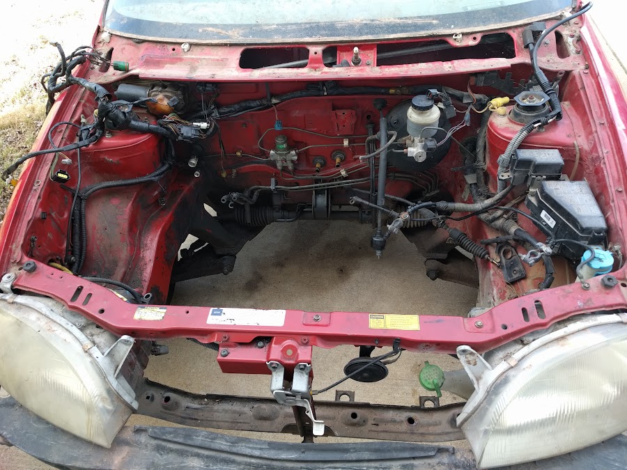
After:


I couldn't contain my excitement, even though I am not ready to install the engine I wanted to test fit it.

I didn't intentionally tease you by not including a picture of the engine hanging in the engine bay. It's just that the engine was hanging, I put it in, I took it out. I didn't snap photos. My bad, as the kids say.
Here are the custom "witness marks" of the crank shaft bolt. Unless, through a 'flash of genius' (or a suggestion from a third party), I come up with a better way I fully intend to drill a 3" hole in the uni-body at that point as relief for the crank bolt. yep, that means to change the fan belt I'll have to take the engine loose from the motor mounts.


Here's an interesting non-engine related WTF moment. I found these marks on the passenger side strut tower:

A previous owner installed these cute spring expander things in the struts on both sides and the passenger side one is getting into the strut tower - that had to make a racket! had to!


 Today
Today