Go Back   EcoModder Forum > EcoModding > Motorcycles / Scooters
Register Now
 Register Now
 

Reply  Post New Thread
 
Submit Tools LinkBack Thread Tools
Old 01-01-2015, 08:55 AM   #11 (permalink)
EcoModding Lurker
 
Join Date: Dec 2014
Location: Florida
Posts: 25
Thanks: 0
Thanked 5 Times in 3 Posts
I would love to know more about what ignition timing and afr you used with diesel. I have had day dreams about diesel in a gas engine but never really looked into it. What advantages have you realized using it?

  Reply With Quote
Alt Today
Popular topics

Other popular topics in this forum...

   
Old 01-01-2015, 12:43 PM   #12 (permalink)
naturalextraction
 
naturalextraction's Avatar
 
Join Date: Mar 2009
Location: New Mexico
Posts: 116
Thanks: 3
Thanked 39 Times in 30 Posts
Thanks greasess for interest in the technology not how i drive. I got rather disenchanted with this thread were sadly the technology is completely overlooked by probably a multitude of "self" reasons related to the psychology of the reader.
The timeing is at stock setting and I don't need to retard timing for the sake of boost as it just would have less power otherwise. I don't have the electronic timing on this EFI to bring timing up under normal operating pressure. So I keep it stock. A/F ratios stay the same although I apparently can run a bit leaner on higher diesel to gasoline ratios or straight diesel. The trick, if you will, is about the surface tension disassociation of the fuel.

I have a device under patent pending status that does work on the fuel before it's introduced to the air induction system. I've been messing with this for about 7 years now and have a multitude of methods in which I've tried to narrow in on one, simplify it greatly and make it a plug and play simply to utilize the fuels readily available and of course get maximum use of the internal chemical potential energy. But this has more to do with over all system configuration as well. Some of the "stuff" you see on the bike in the video is simply there for testing different devices or ease of manipulating configurations.

In theory, it isn't that difficult to utilize the different fuel sources in the ICE and was done much more so in the early years of the ICE's development. Fuels were also quite different and always had much higher surface tensions. The gasolines of today vary widely in it's composition dependent on crude and refinery processes and additives.

The typical composition of gasoline hydrocarbons (% volume) is as follows: 4-8% alkanes; 2-5% alkenes; 25-40% isoalkanes; 3-7% cycloalkanes; l-4% cycloalkenes; and 20-50% total aromatics (0.5-2.5% benzene) (IARC 1989). Additives and blending agents are added to the hydrocarbon mixture to improve the performance and stability of gasoline (IARC 1989; Lane 1980). These compounds include anti-knock agents, anti-oxidants, metal deactivators, lead scavengers, anti-rust agents, anti-icing agents, upper-cylinder lubricants, detergents, and dyes (IARC 1989; Lane 1980). At the end of the production process, finished gasoline typically contains more than 150 separate compounds although as many as 1,000 compounds have been identified in some blends (Domask 1984; Mehlman 1990).

With all that, finding a method to disassociate while not loosing energy to heat absorption and materials is tricky and the largest challenge while still allowing the ICE to utilize internal chemical energy with minimal losses or basically just more efficiently. The ICE alone is not a very efficient power producing component as it is. Thus why we are developing a different turbine type engine of our own with far less parasitic losses and combining it with the efficiency and torque of an electric motor. (The turbine engine is not like a regular turbine much at all fyi but utilizes the basic concept) Which you can read about more in the Energy Extraction blog addressed in the video.

On a side note, I had a Shell chemist arguably (ego) tell me I could not run a gasoline engine on diesel even though agreed the diesel can be refined/disassociated further and is, and once I proved it could be done, consistently, he has never had the courtesy to return my emails even to defend his position. (or ego)

Real science investigation requires you should be wrong every once in awhile if not often to seek out real quantifiable and consistent results. So if I'm wrong thats a good thing and as Dr. Richard Feynman said, "real results also include not denying the real physics involved and being mislead by your own results." It's important to keep testing and investigate all potential mis-observations as well. No pseudoscience crap allowed here.

Last edited by naturalextraction; 01-01-2015 at 12:52 PM..
  Reply With Quote
Old 01-01-2015, 02:18 PM   #13 (permalink)
In Lean Burn Mode
 
pgfpro's Avatar
 
Join Date: Apr 2009
Location: Pacific NW
Posts: 1,531

MisFit Talon - '91 Eagle Talon TSi
Team Turbocharged!
90 day: 39.03 mpg (US)

Warlock - '71 Chevy Camaro

Fe Eclipse - '97 Mitsubishi Eclipse GS
Thanks: 1,262
Thanked 585 Times in 377 Posts
naturalextraction, Thanks for your thread!!!

I have learned a ton from you and your project. Keep up the great work and I hope you will be back here with more information?

Because of you I have now started building a waste solvent system on my Talon project. I have over 500 gallons of free waste solvent for my testing. Most of my waste solvent is made up of Toluene, around 60 to 75 %. So I'm building a pre-heating system. After studying the Honda Mc Laren F1 turbo race cars of the mid to late 80's I decided to run my IAT temps around 158*F and fuel temps around 176*F for fuel atomization? These temps will change once I start testing based on my waste solvent system will only make up 25% or less of total fuel mass?


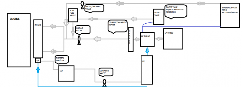
My new Hot/Cold EGR, Waste Solvent Flow Chart.

Modes:

1)Normal. Both systems disabled
2)High Heat, Light Load
3)Hot EGR only, Light to Medium Load
4)Hot EGR, High Heat, Light Load
5)Cold EGR, Light to Medium Load
6)Normal Waste Solvent Light Load
7)High Heat, Waste Solvent, Light Load
8)Hot EGR Waste Solvent, Light Load
9)Hot EGR, High Heat, Waste solvent, Light Load
10)Cold EGR, High Heat, Waste Solvent, Light Load
11)Cold EGR, Waste Solvent, High to Medium Load
12)Boost Tank, Extreme High Load

Anyway keep us informed on your project!!!
__________________
Pressure Gradient Force
The Positive Side of the Number Line


Last edited by pgfpro; 01-01-2015 at 04:55 PM..
  Reply With Quote
The Following User Says Thank You to pgfpro For This Useful Post:
naturalextraction (01-01-2015)
Old 01-01-2015, 02:37 PM   #14 (permalink)
naturalextraction
 
naturalextraction's Avatar
 
Join Date: Mar 2009
Location: New Mexico
Posts: 116
Thanks: 3
Thanked 39 Times in 30 Posts
Hey pgfpro...long time no hear! So glad to see your still progressing with the creative thinking and research. Upon quick review, that looks like a very viable method and your are correct with your temps, although dependent on some other environmental and substance attribute/chemical variables.

I've come up with about the same temperature scaling and my Arduino processors help maintain that delta via some valves that have to move constantly to try and help maintain that. Along with other areas in the environment to help manage temperatures and loss or gain of heat. That is all part of controlling loss of energy within the combusting processes. The thermal couplers helped determine what the real values to be under operating procedures. I've about narrowed in on all of that. Maintaining some form of absolute control is very difficult, or can be do to the multitude of variables from external and internal environmental changes.

After a second look at your flow chart... once you build in values its the start of a good control algorithm. Also keep in mind material absorption rates just like we have in our EFI programing for wall adhesion, with higher heat it is exponential fyi.
  Reply With Quote
The Following User Says Thank You to naturalextraction For This Useful Post:
pgfpro (01-01-2015)
Old 01-01-2015, 02:46 PM   #15 (permalink)
naturalextraction
 
naturalextraction's Avatar
 
Join Date: Mar 2009
Location: New Mexico
Posts: 116
Thanks: 3
Thanked 39 Times in 30 Posts
Are you using wasted heat energy in the "heater" or exchanger or ? sorry, just saw where you are. Controlling that to maintain a delta is a bit of a btch. I use a valving system there as well.
  Reply With Quote
Old 01-01-2015, 03:29 PM   #16 (permalink)
In Lean Burn Mode
 
pgfpro's Avatar
 
Join Date: Apr 2009
Location: Pacific NW
Posts: 1,531

MisFit Talon - '91 Eagle Talon TSi
Team Turbocharged!
90 day: 39.03 mpg (US)

Warlock - '71 Chevy Camaro

Fe Eclipse - '97 Mitsubishi Eclipse GS
Thanks: 1,262
Thanked 585 Times in 377 Posts
One thing I forgot to mention is on my system the waste solvent is just a piggy back system in combination of the normal EFI system? Kind of like a water injection system.

My first test is to bring in the waste solvent system at freeway speed at light load while in lean burn. So EFI Management will be in open loop running on the lean-burn cells in the fuel and timing tables.

I built a manual waste solvent delivery system that uses the HP turbo's compressor housing signal for delivery of hot air (hot air system is copper winding around the inner exhaust pipes, up to 300*F)and waste-solvent. The waste solvent tank is pressurized from the HP turbo and will always run equal too or above the hot air compressor air source. Once the waste-fuel has mixed with the compressor air it will go through a emulsion tube to be atomized even further, then teed off and delivered to the 4 runner direct port intake system. The ports are around 3" from the intake valves.

My original thoughts were to use this system to keep my cat happy and pulse the waste solvent into the engine, acting like a O2 signal cycling.
But then I thought I might as well use the waste solvent for a supplemental fuel that's free to burn and make energy with it.

Anyway enough rambling. lol
__________________
Pressure Gradient Force
The Positive Side of the Number Line

  Reply With Quote
Old 01-01-2015, 03:37 PM   #17 (permalink)
In Lean Burn Mode
 
pgfpro's Avatar
 
Join Date: Apr 2009
Location: Pacific NW
Posts: 1,531

MisFit Talon - '91 Eagle Talon TSi
Team Turbocharged!
90 day: 39.03 mpg (US)

Warlock - '71 Chevy Camaro

Fe Eclipse - '97 Mitsubishi Eclipse GS
Thanks: 1,262
Thanked 585 Times in 377 Posts
Quote:
Originally Posted by naturalextraction View Post
Are you using wasted heat energy in the "heater" or exchanger or ? sorry, just saw where you are. Controlling that to maintain a delta is a bit of a btch. I use a valving system there as well.
Just seen this. I was writing a book above haha.

The waste-solvent heating has a coolant heater at the waste-solvent tank. The compressor housing is drilled and tapped with a 3/8's fitting. Then it goes to the copper tubing wrap around the inner exhaust header pipes. This then goes to the hot air valve, the waste-solvent has its own valve.
__________________
Pressure Gradient Force
The Positive Side of the Number Line

  Reply With Quote
Old 01-01-2015, 04:33 PM   #18 (permalink)
naturalextraction
 
naturalextraction's Avatar
 
Join Date: Mar 2009
Location: New Mexico
Posts: 116
Thanks: 3
Thanked 39 Times in 30 Posts
Im reading at restaurant and probably not absorbing this quite yet....first thing that comes to mind is perculation. I had almost exactly the same arrangements but didnt realize or measure perculation till I was already on the dyno. I was using something similar on my 72 duster. I used a similar method on my big dodge truck with 360 and figured how to control via pressure differential control devices. Had an impressive change to stability of A/F ratio on dyno testing. Amazingly consistent regardless of fuel delivery means, rpm range, load, etc.. Ill write more when im not all thumbs!
  Reply With Quote
The Following User Says Thank You to naturalextraction For This Useful Post:
pgfpro (01-01-2015)
Old 01-01-2015, 04:43 PM   #19 (permalink)
naturalextraction
 
naturalextraction's Avatar
 
Join Date: Mar 2009
Location: New Mexico
Posts: 116
Thanks: 3
Thanked 39 Times in 30 Posts
Also...your efi should pull back on PW with enrichment from your solvent source or any other fuel sources. Thus you should see less gasoline consumption. I have a short video of my device converting motor oil to an easily to light blue flame....a lot of the energy is lost to adhesion as you can emagine.
  Reply With Quote
The Following User Says Thank You to naturalextraction For This Useful Post:
iveyjh (01-01-2015)
Old 01-01-2015, 05:07 PM   #20 (permalink)
In Lean Burn Mode
 
pgfpro's Avatar
 
Join Date: Apr 2009
Location: Pacific NW
Posts: 1,531

MisFit Talon - '91 Eagle Talon TSi
Team Turbocharged!
90 day: 39.03 mpg (US)

Warlock - '71 Chevy Camaro

Fe Eclipse - '97 Mitsubishi Eclipse GS
Thanks: 1,262
Thanked 585 Times in 377 Posts
Quote:
Originally Posted by naturalextraction View Post
Also...your efi should pull back on PW with enrichment from your solvent source or any other fuel sources. Thus you should see less gasoline consumption. I have a short video of my device converting motor oil to an easily to light blue flame....a lot of the energy is lost to adhesion as you can emagine.
So very true.

In my management system I have ability to switch to a secondary map. I'm going to have a manual switch on the hot-air control valve that will activate waste solvent enrichment secondary map.

__________________
Pressure Gradient Force
The Positive Side of the Number Line

  Reply With Quote
The Following User Says Thank You to pgfpro For This Useful Post:
iveyjh (01-01-2015)
Reply  Post New Thread


Powered by vBulletin® Version 3.8.11
Copyright ©2000 - 2024, vBulletin Solutions Inc.
Content Relevant URLs by vBSEO 3.5.2
All content copyright EcoModder.com