 06-20-2009, 05:40 PM
|
#121 (permalink)
|
|
Joe
Join Date: Feb 2009
Location: phx
Posts: 260
Thanks: 0
Thanked 48 Times in 38 Posts
|
Quote:
Originally Posted by arnolde

Say Jyanof, how did you get those nice scope readings? When I hooked up my scope to the input diodes, it blew my stray-current-protector (I'm not sure what the english word for that is) in my fusebox (every German household has one), because the scope ground was basically connected to a power line. So I unclipped that and just left the scope ungrounded and only used the center pin, but those readings were ok but not brilliant. Did you find a different way?
|
arnolde - sorry i didn't reply sooner, but i just saw your post!
yeah, i had that problem too! i think i mentioned using an isolation transformer, but that was the only way i could do it. i bought a used transformer from the surplus store that had multiple taps for input and output. i used the combinations of taps that made it a 1:1 transformer and now the inputs to the charger are isolated from the house wiring. It worked well, but it was only a 1kVa transformer, so I could only use it at low power (it got pretty warm at 5A). for high power stuff, I just assumed that the circuit behaved the same when it wasn't isolated and removed the isolation transformer.
my dad had a suggestion of using optoisolators somehow to isolate the scope probes. since the transformer worked for me, i didn't look into how to do that.
have you had any luck?
|
|
|

|
 Today Today
|
|
|
|
 Other popular topics in this forum...
|
|
|
|
|
07-01-2009, 03:43 AM
|
#122 (permalink)
|
|
Joe
Join Date: Feb 2009
Location: phx
Posts: 260
Thanks: 0
Thanked 48 Times in 38 Posts
|
Progress update!
I put together a PCB board for the power section and opto-isolated it from the control board.
The test mentioned earlier was performed : Use a pot to control PWM from the micro; have a second pot to increase the duty cycle by 1 bit in order to determine the change in amps due to a single increment in duty cycle.
The micro was run with a 16 mhz crystal in fast pwm mode with 9 bit resolution (512 total divisions). In this mode, the switching frequency is about 31 khz.
Results:
Up to ~5 amps, the charger was in discontinuous current mode and was not sensitive to a small change in duty cycle.
Above 5 amps, a single increment in duty cycle increases the output current by about .5 amps.
I think this'll be ok. Towards the end of charge, the charger should be able to control current finely , if needed. Otherwise, during bulk charging, I think half an amp is enough resolution to control current.
One thing I had thought about was dithering the duty cycle - like, one cycle would have dutycycle = 100, and the next would have dutycycle=101, and duty cycle would alternate between the 2 every cycle. might provide some finer resolution?
pictures in the next post...
|
|
|
|
|
07-01-2009, 04:00 AM
|
#123 (permalink)
|
|
Joe
Join Date: Feb 2009
Location: phx
Posts: 260
Thanks: 0
Thanked 48 Times in 38 Posts
|
pictures!
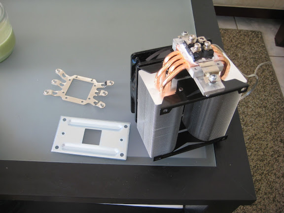
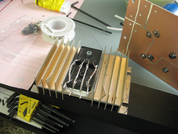
changing the mosfet mounting:
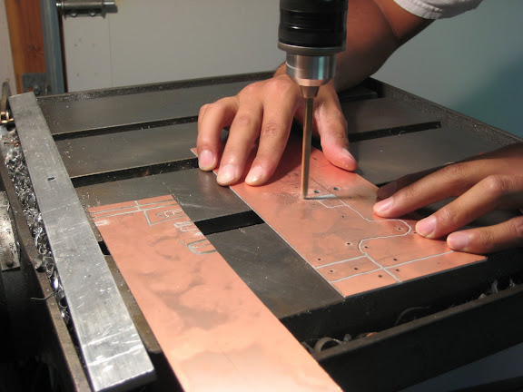
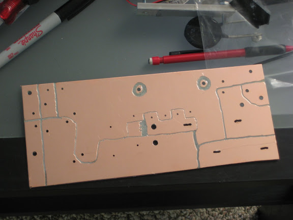
the PCB layout and the beginning cuts
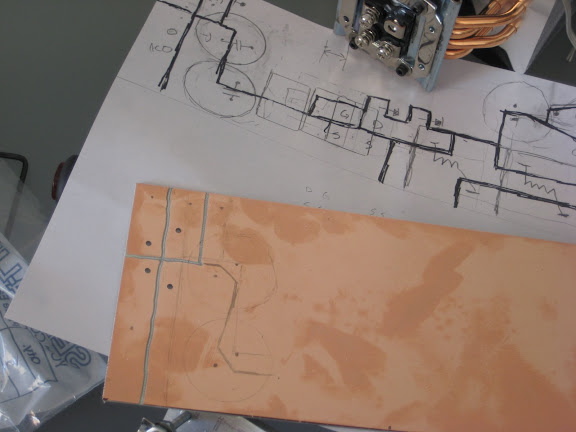
i just used a drill bit to mill away the copper and moved the board around by hand. kinda sloppy, but didn't take too long.
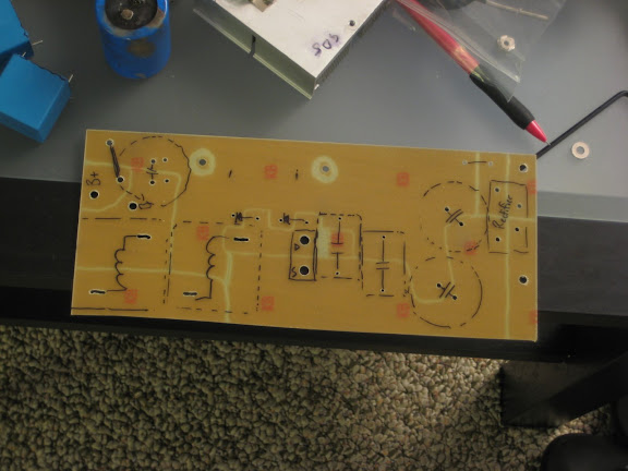
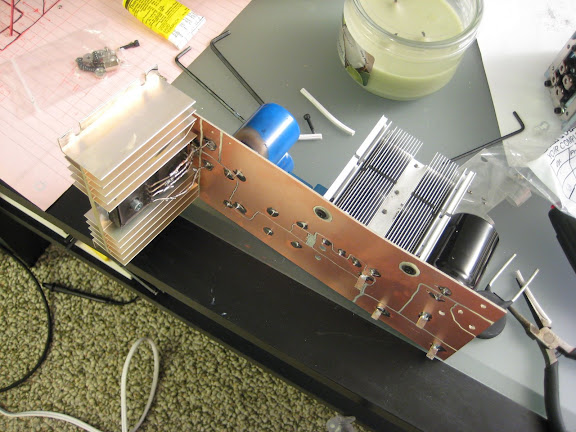
the completed board
I tried to draw the components on the otherside... good thing too, cuz i actually ran into a problem with the capacitor in the top left - had to drill an extra set of holes.
the diodes in place:
i used some mosfet clamps to spring-load the screws. prbably not the best method - it kinda bent the board.
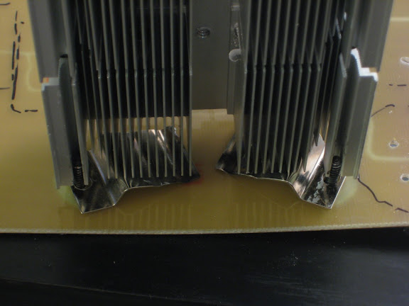
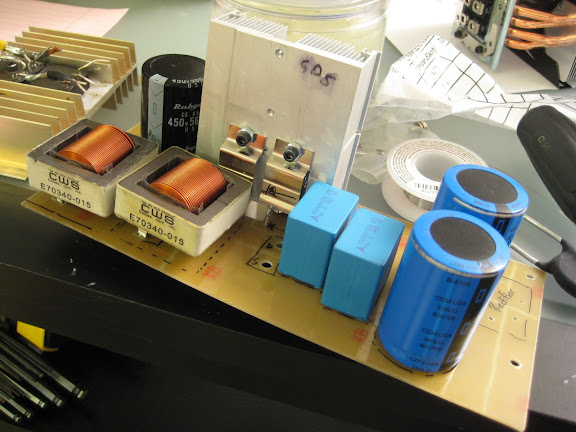
two paralleled rectifier bridges
and mounted
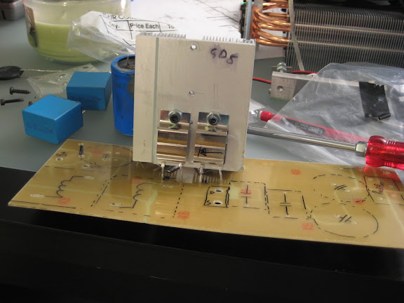
all the caps and inductors mounted. i should add that all of this mounting stuff is preliminary. now that i know the arrangement and layout seem to work, i'd probably try to figure out a better way of mounting the components so that it's not just the solder holding them in. also, I'm kind of using the pcb board as a structural member. I'm sure that isn't the best thing either...
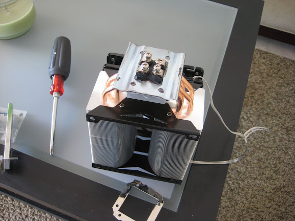
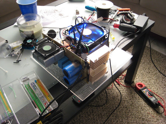
the mosfet and heatsink bolt onto the otherside. you can see the control board with two small pots that i had to turn with the yellow screwdriver. the picture had knobs.
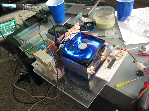
another view - if you're curious about size, the piece of plexiglass that it's on is 11x11. It'd be smaller too if it weren't for that ridiculous heatsink!
 |
|
|
|
|
07-01-2009, 04:10 AM
|
#124 (permalink)
|
|
Joe
Join Date: Feb 2009
Location: phx
Posts: 260
Thanks: 0
Thanked 48 Times in 38 Posts
|
oh yeah, next test:
automatic current control! i have a 50A hall effect current sensor and need to get it wired up. once i know it works and reads correctly, i'll have to write some code to hold the current at whatever the user defines.
after that is voltage control for the constant voltage phase...
|
|
|
|
|
07-01-2009, 01:18 PM
|
#125 (permalink)
|
|
EcoModder Student
Join Date: Nov 2008
Location: Youngsville, NC
Posts: 117
Thanks: 11
Thanked 14 Times in 13 Posts
|
jyanof,
This is fantastic progress 
Keep it up. I for one am following intensely. The idea of having a diy open source charger along side of a diy open source controller certainly reflects the generous nature of these projects. The whole EV world awaits these projects. There are scores of folk with limited budgets who will benefit from your work.I can breath better already.
Awesome work
You and Paul are from the same mold. 
Thank you for all you are doing.
Eric
__________________
1995 BMW 318i EV in the making
|
|
|
|
|
07-02-2009, 12:20 AM
|
#126 (permalink)
|
|
EcoModding Lurker
Join Date: May 2009
Location: Bremerton, Wa
Posts: 41
Thanks: 0
Thanked 0 Times in 0 Posts
|
Wow, great progress. I was wondering when the next update would come, but from what I've seen...you make a load of progress, then post in one big batch, which just makes a pile of surprises. Keep it up!
|
|
|
|
|
07-02-2009, 01:00 AM
|
#127 (permalink)
|
|
PaulH
Join Date: Feb 2008
Location: Maricopa, AZ (sort of. Actually outside of town)
Posts: 3,832
Thanks: 1,362
Thanked 1,202 Times in 765 Posts
|
just too awesome for words! I can't wait for that constant current constant voltage stuff! A real life charging algorithm emerging right before our eyes! Awesome Job! I love your etching too! Very creative! Yoooooooo Joe! A real american Hero!
|
|
|
|
|
07-02-2009, 05:15 AM
|
#128 (permalink)
|
|
Joe
Join Date: Feb 2009
Location: phx
Posts: 260
Thanks: 0
Thanked 48 Times in 38 Posts
|
hey guys, thanks for the kind words! feelin like we're getting close...
i've been working on this constant current stuff most of the day today and it's kinda thrown me for a loop. (pun intended?)
first, i had to have -5V and +5v on the current sensor in order to get it to work - Paul, you didn't run into this problem? i'm using the 50A tamura current sensor...
then, i spent a ton of time playing with control algorithms. having PWM increment if the current was too high or too low caused the current to oscillate. there was ~400hz sine wave when I put the scope across the current sensor output.
next I tried a PD loop, but that caused some weird things to happen. very noisy current signal, bouncing around a lot between two values.
i tried a few other things, but it seems just basic low value
proportional control works best.
it still does some weird things at certain current settings. like, makes noise and the control loop goes a little unstable.
i'll play with it more tomorrow...
|
|
|
|
|
07-02-2009, 12:05 PM
|
#129 (permalink)
|
|
PaulH
Join Date: Feb 2008
Location: Maricopa, AZ (sort of. Actually outside of town)
Posts: 3,832
Thanks: 1,362
Thanked 1,202 Times in 765 Posts
|
I used this part for the ebike controller:
Digi-Key - 620-1110-ND (Allegro Microsystems Inc - ACS755LCB-050-PFF)
Zero current corresponds to an output of 0.6v, and each amp increase corresponds to an increase of 60mV on the output. It's powered by a 5v supply, and can safely be used to measure current in the range of 0 to 50 amps. The most amps it can handle is 200. It worked very well and seemed very well suited to the A/D input of a uController.
What was the amplitude of the 400 Hz sine wave? (aka, how bad was the overshoot for the current?)
When I needed greater resolution of pwmDuty because current was changing too fast, I just incremented and decremented a virtual PWM duty variable that has a very large resolution, like 0-16383. Then when I was ready to find the actual pwmDuty value, I would map it onto 0-511, taking rounding into account. It worked really well. At low RPM, when the current can change the fastest, the current changed incredibly slow. It basically had the same effect as the dithering you were talking about. I think you could use a HUGE virtual pwmDuty (a long int), and just increment or decrement it by 1, since it doesn't have to respond as fast as a throttle.
Last edited by MPaulHolmes; 07-03-2009 at 12:01 AM..
Reason: 0-511, not 0-512! hehe.
|
|
|
|
|
07-02-2009, 02:23 PM
|
#130 (permalink)
|
|
Joe
Join Date: Feb 2009
Location: phx
Posts: 260
Thanks: 0
Thanked 48 Times in 38 Posts
|
Quote:
Originally Posted by MPaulHolmes
What was the amplitude of the 400 Hz sine wave? (aka, how bad was the overshoot for the current?)
|
the amplitude was about 100mV which corresponds to about 1.5A. so, my clamp meter would show 4.7 amps (which was about right) but the scope was showing it as an oscillation +- 1.5A.
of course, btw, this is all being tested on a resistive heater element. it's easier to work with, but I know the battery will be much more sensitive.
I like the idea of the finer resolution variable - was wondering what that was all about, but now it makes sense. Otherwise, it won't work too well if your "changeinPWM" variable always gets rounded to zero. I'll give it a shot!
|
|
|
|
|


