12-08-2010, 12:28 PM
|
#21 (permalink)
|
|
needs more cowbell
Join Date: Feb 2008
Location: ÿ
Posts: 5,038
Thanks: 158
Thanked 269 Times in 212 Posts
|
for whatever reason, doing a digital read in the interrupt wasn't working reliably when I tried it. I have considered toggling the interrupt direction in the interrupt, but with there being spare pins already it seemed like another sort of obsessive optimization 
__________________
WINDMILLS DO NOT WORK THAT WAY!!!
|
|
|

|
 Today Today
|
|
|
|
 Other popular topics in this forum...
|
|
|
|
|
12-08-2010, 12:45 PM
|
#22 (permalink)
|
|
EcoModding Lurker
Join Date: Feb 2009
Location: Ontario, Canada
Posts: 35
Thanks: 2
Thanked 14 Times in 7 Posts
|
Quote:
Originally Posted by dcb

for whatever reason, doing a digital read in the interrupt wasn't working reliably when I tried it. I have considered toggling the interrupt direction in the interrupt, but with there being spare pins already it seemed like another sort of obsessive optimization |
Ha-ha ... splitting the functions apart and connecting them again with I2C ... that's excessive too.
dbc, your MPGuino is great - it got me into the Arduino in a bigger way, for which I thank you! |
|
|
|
|
The Following User Says Thank You to mluckham For This Useful Post:
|
dcb (12-08-2010) |
|
12-08-2010, 02:05 PM
|
#23 (permalink)
|
|
EcoModding Apprentice
Join Date: Jan 2010
Location: Newark, DE
Posts: 143
Thanks: 0
Thanked 14 Times in 14 Posts
|
Quote:
Originally Posted by mluckham
splitting the functions apart and connecting them again with I2C... that's excessive too.
|
Well, without the expander we'll have what? One digital I/O pin free?. Per-pin, digital I/O is cheap. That 8-bit port costs about the same as a single channel I2C ADC. Also, some of the digital lines on the Arduino have PWM functionality as seen with the display backlight dimming... The expander can't do that.
If your focus is on what we already have, then yes everything is fine and dandy the way it is right now. If you focus on making the system more adaptable, adding new features, functionality and such, some hardware upgrades and reworks would be highly conducive to that outcome and therefore seem perfectly reasonable to me.
The second interrupt line could be used to measure some other PWM-based sensor (I seem to recall hearing that some cars used a PWM-based VSS?), a second injector on dual-stage setups such as the DPFI TBI used on '88-91 Civics/CRXs, or could be hooked up to the interrupt output from the port expander, triggering an input-update routine.
Personally, I would like to get both the character display and buttons on the I2C bus. That way the Arduino "brain" could be located where ever is convenient (close to the ECM, somewhere central behind the dash, whatever) while the display and buttons are situated in easy view/reach, with a 5 wire umbilical (2 power, 2 I2C, 1 backlight control) between them.
Why? The display unit could be put pretty much anywhere, including being built into the OEM clock housing:
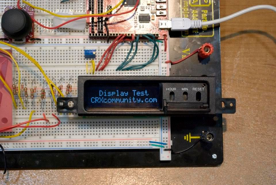
Yeah, you can do that without I2C but the umbilical ends up being a 1/2", 13 wire mass.
What about the clock functionality? An I2C real time clock chip could keep track of the time and date, running off a coin cell when the rest of the system is switched off.
|
|
|
|
|
12-08-2010, 03:15 PM
|
#24 (permalink)
|
|
needs more cowbell
Join Date: Feb 2008
Location: ÿ
Posts: 5,038
Thanks: 158
Thanked 269 Times in 212 Posts
|
Quote:
Originally Posted by bobski
Well, without the expander we'll have what? One digital I/O pin free?
|
I'm not trying to bust your chops here bob, just clarifying.
looking at the 328 schematic, I see 2 analog and 2 pwm pins, and rx and tx if you don't need a bootloader http://opengauge.googlecode.com/svn/...no/mpguino.png
though tx can be hooked up directly to this sd card logger
http://ecomodder.com/forum/showthrea...ger-15066.html
Quote:
Originally Posted by bobski
Yeah, you can do that without I2C but the umbilical ends up being a 1/2", 13 wire mass.
|
I understand that you are targeting the arduino platform, but the cpu and support components all fit nicely behind the lcd with a custom pcb, and the whole unit only needs 4 wires to hook up. Certainly your component count is going up here too. Can you pwm the contrast/brightness via i2c?
__________________
WINDMILLS DO NOT WORK THAT WAY!!!
|
|
|
|
|
12-08-2010, 04:33 PM
|
#25 (permalink)
|
|
EcoModding Apprentice
Join Date: Jan 2010
Location: Newark, DE
Posts: 143
Thanks: 0
Thanked 14 Times in 14 Posts
|
Quote:
Originally Posted by dcb
looking at the 328 schematic, I see 2 analog and 2 pwm pins, and rx and tx if you don't need a bootloader
[...]
I understand that you are targeting the arduino platform
|
Right. I was ruling out special-purpose pins like rx(0), tx(1) and I seem to recall the pin with an attached on-board LED having something to do with programming, but I see now that's pin 13 which is in use by the LCD. So yeah, there's two digital pins.
My line of thought on the analog side was that if we relocate the button signals to different analog pins, then use analog 4 and 5 for I2C, all the analog inputs will be occupied.
Quote:
Originally Posted by dcb
but the cpu and support components all fit nicely behind the lcd with a custom pcb, and the whole unit only needs 4 wires to hook up.
|
Which is great as a finished product but it doesn't leave any room for expansion, tinkering or innovation in general. Reorganizing things for the sake of tinkerers seems backwards right up until those tinkerers come up with some cool add-on that the average users want. At that point, the neat packaging of the finished device becomes a limitation rather than a benefit.
Quote:
Originally Posted by dcb
Can you pwm the contrast/brightness via i2c?
|
It's possible I'm sure, but the chip I listed won't do it. If you're willing to step away from chips with a hard-wired purpose, the ATtiny series (the ATmega's little brother) has similar analog input, digital I/O, PWM and I2C capabilities, but in a smaller footprint. The largest chip design (ATtiny*61A) is a 20 pin standard-width DIP package with 16 I/O lines, 11 of which have 10-bit ADC functionality, and 3 PWM channels on 6 pins (3 inverting, 3 non-inverting outputs). 2, 4 or 8k of in-system programmable flash storage (the * in the part number), 128, 256 or 512 bytes of ram (respectively), an on-board oscillator running at up to 20 Mhz, external and internal interrupt sources, on-chip temperature sensor, etc., etc., etc.
This all comes down to about $3/chip. The smaller (mostly just fewer I/O lines) go for as little as $2/chip. They sound awesome but I doubt the Arduino IDE supports them (in spite of them sharing AVR architecture), and I don't like the thought of programming serial comms in assembly.
Last edited by bobski; 12-08-2010 at 04:42 PM..
|
|
|
|
|
12-08-2010, 06:06 PM
|
#26 (permalink)
|
|
needs more cowbell
Join Date: Feb 2008
Location: ÿ
Posts: 5,038
Thanks: 158
Thanked 269 Times in 212 Posts
|
Quote:
Originally Posted by bobski
Right. I was ruling out special-purpose pins like rx(0), tx(1) and I seem to recall the pin with an attached on-board LED having something to do with programming, but I see now that's pin 13 which is in use by the LCD. So yeah, there's two digital pins.
|
well, all the pins I listed can be used as general i/o digital pins, so technically there are 6 available. You might want to avoid rx so as to have an easier time with the bootloader.
Quote:
Originally Posted by bobski
My line of thought on the analog side was that if we relocate the button signals to different analog pins, then use analog 4 and 5 for I2C, all the analog inputs will be occupied.
|
FYI, with a couple resistors you can "multiplex" several buttons onto one analog pin. It's how the buttons on my saturns cruise control works. http://i13.tinypic.com/80uib5y.jpg
Quote:
Originally Posted by bobski
Which is great as a finished product but it doesn't leave any room for expansion, tinkering or innovation in general.
|
I think that really depends on the tinkerer. I'm reminded of brandonU's powning of a usb cable, though the writeup is gone now: http://ecomodder.com/forum/showthrea...html#post37599 , basically, if you can see or hack your way to the leads, you can tinker/expand/modify/innovate anything, just not in lego fashion.
Doing what the OP was requesting, adding logging, means adding one wire to the unit (3 if you want to borrow 5 volts and ground).
Quote:
Originally Posted by bobski
They sound awesome but I doubt the Arduino IDE supports them (in spite of them sharing AVR architecture), and I don't like the thought of programming serial comms in assembly.
|
There are arduino options there, as well as possibly taking a dremel to a mega 328  Arduino Forum - sizing down my arduino
__________________
WINDMILLS DO NOT WORK THAT WAY!!!
Last edited by dcb; 12-09-2010 at 08:01 AM..
|
|
|
|
|
12-08-2010, 06:17 PM
|
#27 (permalink)
|
|
EcoModding Lurker
Join Date: Feb 2009
Location: Ontario, Canada
Posts: 35
Thanks: 2
Thanked 14 Times in 7 Posts
|
Quote:
Originally Posted by dcb
with a couple resistors you can "multiplex" several buttons onto one analog pin[/url]
|
I like this idea.
Quote:
Originally Posted by dcb
|
I use the Spiffie MPGuino which has USB, and also have replaced the '168 with a '328. |
|
|
|
|
12-09-2010, 02:57 AM
|
#28 (permalink)
|
|
EcoModding Lurker
Join Date: Sep 2010
Location: Fresno, CA
Posts: 78
Thanks: 4
Thanked 9 Times in 7 Posts
|
edit: holy crap, there's another page there. so disregard this post for now... lol.
Quote:
^ Obsessive optimization, but it pays off, the code runs very reliably.
The two pins for injector pulses makes sense, I saw that right off the bat when I looked at the code - one interrupt for rising, one for falling, and it times the difference between the two. Very smart decision there.
What I don't understand is why the LCD data pins are such a spaghetti rat's mess - pins 13, 12, 8, and 7 for bits 3, 2, 1, and 0, for each single character... why not just wired straight across digital 13-12-11-10 - why the break in pins? And the analog pins aren't tied to interrupts (right?), so why separate the VSS signal analog pin from the button pins? - why not just go 0-1-2-3?
Just curious about the design decisions... if those turn out to be silly, then I'll start criticizing 
|
|
|
|
|
|
12-09-2010, 03:02 AM
|
#29 (permalink)
|
|
EcoModding Lurker
Join Date: Sep 2010
Location: Fresno, CA
Posts: 78
Thanks: 4
Thanked 9 Times in 7 Posts
|
Quote:
Originally Posted by bobski
What about the clock functionality? An I2C real time clock chip could keep track of the time and date, running off a coin cell when the rest of the system is switched off.
|
Actually don't even need a battery backed RTC... I already wrote a RTC add-in for MPGuino that's kept perfect time for weeks now! Amazingly enough, the "loops" in the MPGuino code are absolutely perfectly timed at 500ms, which can be used in a "clock counter" that counts seconds past a predetermined time (although now that I think about it, I could really just count "seconds from midnight"... eugh, sometimes I complicate things). One of the many things I learned to hack together in the MPGuino code |
|
|
|
|
12-09-2010, 07:58 AM
|
#30 (permalink)
|
|
needs more cowbell
Join Date: Feb 2008
Location: ÿ
Posts: 5,038
Thanks: 158
Thanked 269 Times in 212 Posts
|
re: spaghetti wiring, the lcd connections were originally chosen to be pretty much a straight shot from the digital pins layout on an arduino while leaving the special purpose pins open (pwm/uart). Then I realized contrast could be controlled in software so I moved the contrast lcd lead over to a pwm pin. If you look at the diagram http://opengauge.googlecode.com/svn/...ino/wiring.GIF you will notice most of the lcd leads that go directly to the arduino do not cross, except the contrast lead from lcd3 to arduino 6. The other connections to the lcd are the ground "bus", 5 volts from the other side of the board, and backlight power (pwm'd via an external transistor controlled via arduino 9).
Since that side of the board was already so crowded, I started using the pins on port C for buttons/speed.
re: interrupts, Both vehicle speed and buttons are handled by the same interrupt, since ultimately they are on the same port once you decode the arduino pin wiring http://arduino.cc/en/uploads/Hacking...mega8-Pins.png. I think arduino interrupts were limited to just the two INT0 and INT1 when this was written, and arduino wrappers soak up performance and resources anyway. It is much tighter to read all the port pins into a byte with one instruction, which is especially critical in an interrupt.
//attach the vss/buttons interrupt
ISR( PCINT1_vect )
{
static byte vsspinstate = 0;
byte p = PINC;//bypassing digitalRead for interrupt performance
Also, at the time there was discussion about using a pwm to drive a piezo on pin 10 to do various "chimes" as another feedback channel:
http://www.arduino.cc/cgi-bin/yabb2/...num=1228475606
__________________
WINDMILLS DO NOT WORK THAT WAY!!!
Last edited by dcb; 12-09-2010 at 08:22 AM..
|
|
|
|
|