 09-17-2014, 07:09 PM
|
#1121 (permalink)
|
|
EcoModding Apprentice
Join Date: Feb 2010
Location: Northern Wisconsin
Posts: 137
Thanks: 32
Thanked 39 Times in 23 Posts
|
Quote:
Originally Posted by e*clipse

On another note, I really need to look into the sources of those noise pulses closer. For example, I'm doing all this on a solderless breadboard. These are known to be the worst noisiest option out there. Simply using a proper PC board with a ground plane and well designed circuitry could get rid of most of the other spikes. I would like to use through hole components so anyone could assemble them, but surface mount components do have EMI advantages. I've soldered a lot of surface-mount components in my toaster oven. 
- E*clipse
P.S. - e-mail coming |
On most of the breadboards I've tested in a noisy environment I have put massive numbers of .1 and .01 caps on all chip power leads as close as I can to the chips - and place them on all power lead, regulators etc... Helps so much to quench those transient spikes...
__________________
Dave  ...
|
|
|

|
|
The Following 2 Users Say Thank You to dave koller For This Useful Post:
|
|
 Today Today
|
|
|
|
 Other popular topics in this forum...
|
|
|
|
 09-17-2014, 07:25 PM
|
#1122 (permalink)
|
|
Permanent Apprentice
Join Date: Jul 2010
Location: norcal oosae
Posts: 523
Thanks: 351
Thanked 318 Times in 215 Posts
|
Oh, now that's almost funny! 
Of course - with slip, it IS worthless. For my motor with the reluctance torque, it's merely a fuzzy helpful (maybe) value. Since we're not doing servo stuff, the wheel's position isn't important either. whew! That sure took me a while to digest. 
For noise concerns, I think it might be best for me to make this SMT, and use the other side for a ground plane. I'd hate for my board to cause issues on the main board. I'll also try to remind myself how not to infect the power sources. 5V, 12V.
- E*clipse
Quote:
Originally Posted by MPaulHolmes

Index is worthless for AC controllers. And for a resolver, where we are getting sine and cos values, index would also be worthless! So yes! Index officially becomes available.
I think you are right. As long as the microcontroller is receiving 2 voltages that correspond to sin and cos (or some distortion thereof) it's all good. And you are also right about those breadboards at high frequency, with edges. Absolute worst case scenario. That's actually another reason why I think it would be good to keep the high frequency pulses contained to your board. If it has to travel far along a pair of wires, that's going to have inductance, and then spikes as a result.
|
|
|
|

|
 09-17-2014, 07:49 PM
|
#1123 (permalink)
|
|
Permanent Apprentice
Join Date: Jul 2010
Location: norcal oosae
Posts: 523
Thanks: 351
Thanked 318 Times in 215 Posts
|
Hi Dave!
A quick question about the spikes - they don't show up in the oscilloscope plots, even if I speed up the scope to where I see only part of the waveform. This shows up in the spectrum analyzer. How does that work? Am I getting paranoid about something that is barely visible? Then, at the resolver's zero crossings, there's a bunch of crap. Seriously crap - I don't know a better way to describe it. If I use my signal generator for a resolver input, it goes smoothly to zero, so I'm guessing it's not the resolver.  From what I can see, there are no odd shifts or other hints that something's wrong at the zero crossing. 
I'm using decoupling caps on every op-amp. You are suggesting microFarad sized caps, right? 
I'm running 0.1 uF ceramic caps on every op-amp. Apparently that's not enough - the Microchip App note advised 1.0uF ceramic caps **in addition** to the 0.1uF caps.
The ST app note doesn't mention anything larger than the 0.1uF caps, although I did run two 10uF electrolytic caps on a previous design, one for the positive and one for the negative supply. This is a single supply design, and I was considering 10uF to help it out.
A few other app-note suggestions I'd like to run by folks:
1) a capacitor at the power op-amp's output, with a very small resistor to ground -because this is driving an inductive load, the "Boucherot cell" concept.
2) a high value (M Ohm) resistor to ground right after the decoupling capacitor at the filter op-amp's input
Thank you very much for your help! 
- E*clipse
Quote:
Originally Posted by dave koller

On most of the breadboards I've tested in a noisy environment I have put massive numbers of .1 and .01 caps on all chip power leads as close as I can to the chips - and place them on all power lead, regulators etc... Helps so much to quench those transient spikes...
|
|
|
|

|
 09-18-2014, 12:05 PM
|
#1124 (permalink)
|
|
PaulH
Join Date: Feb 2008
Location: Maricopa, AZ (sort of. Actually outside of town)
Posts: 3,832
Thanks: 1,362
Thanked 1,202 Times in 765 Posts
|
Op amps are like the great unknown to me. I got used to them a little bit on a project I did, but I know almost nothing about them, and the tricks involved in getting them to behave. I only did math in school, and they skipped op amps in my math classes. haha.
I just ordered 2 LEM Hass 50-s current sensors for testing the motor outside. I also found out that the control technique for GRID TIE (3 phase) is identical to standard field oriented control with a synchronous motor. The grid is a motor in either regen or "not regen" state.
I need to solder those dang control boards tonight.
Last edited by MPaulHolmes; 09-18-2014 at 12:12 PM..
|
|
|

|
 09-18-2014, 03:16 PM
|
#1125 (permalink)
|
|
EcoModding Apprentice
Join Date: Feb 2010
Location: Northern Wisconsin
Posts: 137
Thanks: 32
Thanked 39 Times in 23 Posts
|
Quote:
Originally Posted by e*clipse

Hi Dave!
A quick question about the spikes - they don't show up in the oscilloscope plots, even if I speed up the scope to where I see only part of the waveform. This shows up in the spectrum analyzer. How does that work? Am I getting paranoid about something that is barely visible? Then, at the resolver's zero crossings, there's a bunch of crap. Seriously crap - I don't know a better way to describe it. If I use my signal generator for a resolver input, it goes smoothly to zero, so I'm guessing it's not the resolver.  From what I can see, there are no odd shifts or other hints that something's wrong at the zero crossing. 
- E*clipse |
If you use .001 next to the .1 or .01 it captures high frequency pulses.. the power bus lines should also include 10 mfd and 40 mfd and even 100 - 200 mfd to stabilize the power lines as your signal generator provides... I overdo the power buses always. I have had some circuits take a bit to power down from all the caps 
__________________
Dave  ...
|
|
|

|
|
The Following 4 Users Say Thank You to dave koller For This Useful Post:
|
|
 09-20-2014, 11:11 PM
|
#1126 (permalink)
|
|
PaulH
Join Date: Feb 2008
Location: Maricopa, AZ (sort of. Actually outside of town)
Posts: 3,832
Thanks: 1,362
Thanked 1,202 Times in 765 Posts
|
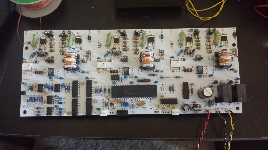
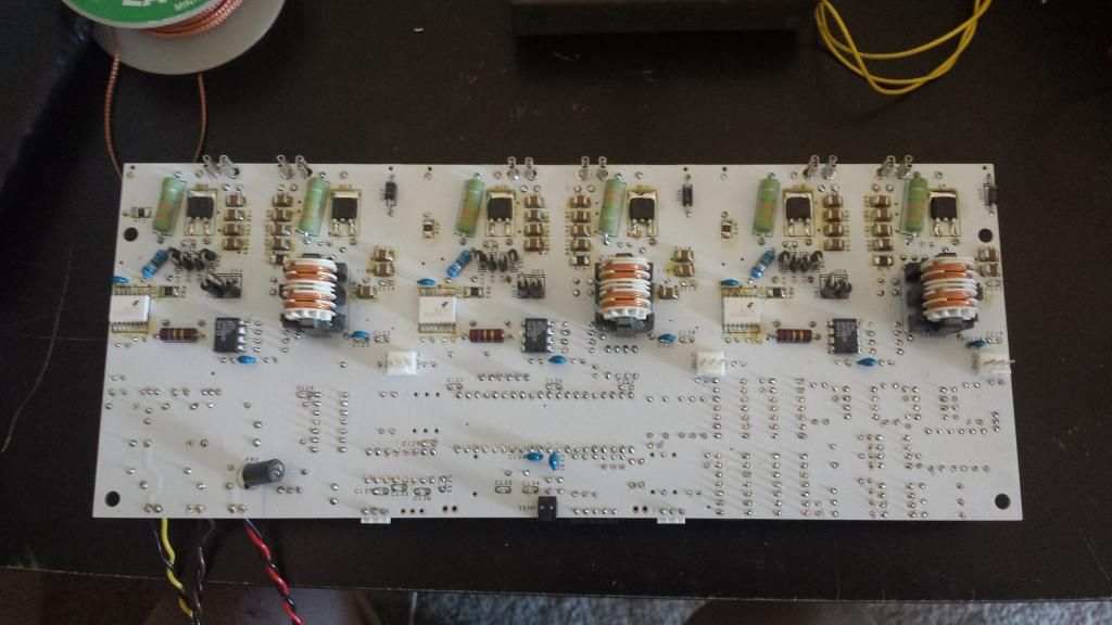
Top: 
Bottom:  |
|
|

|
|
The Following 4 Users Say Thank You to MPaulHolmes For This Useful Post:
|
|
 09-20-2014, 11:26 PM
|
#1127 (permalink)
|
|
EcoModding Lurker
Join Date: Apr 2014
Location: seattle
Posts: 23
Thanks: 33
Thanked 11 Times in 10 Posts
|
how long did it take to solder all that up? with an iron or another method?
|
|
|

|
 09-20-2014, 11:35 PM
|
#1128 (permalink)
|
|
PaulH
Join Date: Feb 2008
Location: Maricopa, AZ (sort of. Actually outside of town)
Posts: 3,832
Thanks: 1,362
Thanked 1,202 Times in 765 Posts
|
I have your package next to the door. I just need to mail it. Dang it. Its just that the post office is like 30min away, and I forgot.
It took about 7 hours, all by hand. The surface mount part isnt too bad. The smallest sm parts are 1210.
I've tested the 6 isolated supplies. So far so good.
Last edited by MPaulHolmes; 09-20-2014 at 11:40 PM..
|
|
|

|
|
The Following 3 Users Say Thank You to MPaulHolmes For This Useful Post:
|
|
 09-20-2014, 11:39 PM
|
#1129 (permalink)
|
|
EcoModding Lurker
Join Date: Apr 2014
Location: seattle
Posts: 23
Thanks: 33
Thanked 11 Times in 10 Posts
|
no worries, i do not start fall quarter till the 29th and i wont get started on projects until a few weeks after that, yeah i know what you mean, I am looking at property out fall city in the middle of the forest and its gunna be a trek to go anywhere
|
|
|

|
 09-21-2014, 02:42 PM
|
#1130 (permalink)
|
|
Master EcoModder
Join Date: Aug 2012
Location: northwest of normal
Posts: 29,458
Thanks: 8,383
Thanked 9,141 Times in 7,547 Posts
|
Falls City, OR? My niece says that's the head of a bike trail through the Coast Range to the Pacific. 
You used to be able to take a back street out of Falls City and go up to Valsetz, a company logging town. It's gone now. 
|
|
|

|
|