 07-12-2014, 12:18 AM
|
#851 (permalink)
|
|
Master EcoModder
Join Date: Sep 2010
Location: Saskatoon, canada
Posts: 1,488
Thanks: 746
Thanked 565 Times in 447 Posts
|
Quote:
Originally Posted by MPaulHolmes

One limit is the very high voltage associated with it. But maybe you could build a boost stage that takes maybe 150v and sends it up to 300v, and then use that for the bus for the AC controller.
|
Batteries can be had in smaller amp-hour sizes (25, 40, 60 amp-hour) so you can avoid the boost converter (more weight, lower peak current) if you are OK with double or triple the battery connections. 320V of LiFePO4 cells is 100 in series. Using 40 a-h cells, you get a 12 kw-h pack. Not sure what sort of range you are looking for.
|
|
|

|
 Today Today
|
|
|
|
 Other popular topics in this forum...
|
|
|
|
|
07-12-2014, 12:24 AM
|
#852 (permalink)
|
|
Master EcoModder
Join Date: Sep 2010
Location: Saskatoon, canada
Posts: 1,488
Thanks: 746
Thanked 565 Times in 447 Posts
|
Quote:
Originally Posted by MPaulHolmes
The 2 film caps arrived yesterday. So, I have the IGBTs, cap... Now I'm waiting on performance data from the DC controllers (the driver section) to see if I need to change anything for the AC driver section before I send that board in to be manufactured. Then it's easy peasy, japanezy. bam done! haha. more or less.
|
The IGBTs are rated at 600V, 600A, right?
How much heat can the heat sink get rid of, even with liquid cooling?
So is 250V, 200 amps a reasonable limit to start with? I guess I need to start looking for an AC motor! |
|
|
|
|
07-24-2014, 08:20 PM
|
#853 (permalink)
|
|
Dreamer
Join Date: Nov 2013
Location: Australia
Posts: 350
Thanks: 95
Thanked 214 Times in 151 Posts
|
Quote:
Originally Posted by MPaulHolmes
Take your time deciding on a contactor. I just lost around 16 hours of work (over the last 2 days) on the PCB, because it got corrupted by DesignSpark! They are working on it, to see if it can be recovered. Most of the time was spent on the layout for the driver section. Well, I finally decided on a good driver section layout. They can't erase it from my mind! The schematic part is done now. So, it's just laying it out and routing it again, and hoping it doesn't happen again. I reinstalled designSpark. Hopefully that will help.
...
|
Quote:
Originally Posted by Astro
Ouch, having to do all that rework is horrible.
Best to think of it as a chance to improve upon what you lost. 
Not sure how to put a positive spin on the lost 16 hours tho. |
Quote:
Originally Posted by MPaulHolmes
I've finally got a new layout that is BETTER than before! Hurray! It was worth losing the other one. Well, they are similar to each other, but this one is a tiny bit better. The driver section symmetry is so glorious I can hardly stand it. haha. I want to tell it to stop being beautiful, but it just won't listen!
|
Sounds good. Symmetry is good, makes fault finding easier.
Of course any bugs in the design will be repeated in each driver section.
Also have to say, your post lacked the pictures that would have enabled the rest of us to bask in the radiant glow of the improved driver sections.
PS. Moved the reply over to this thread as i think it fits better than in the contactor thread.
Last edited by Astro; 07-24-2014 at 08:21 PM..
Reason: Spelling, doh.
|
|
|
|
|
The Following User Says Thank You to Astro For This Useful Post:
|
|
|
07-29-2014, 08:15 PM
|
#854 (permalink)
|
|
PaulH
Join Date: Feb 2008
Location: Maricopa, AZ (sort of. Actually outside of town)
Posts: 3,832
Thanks: 1,362
Thanked 1,202 Times in 765 Posts
|
Control board/Driver board "done" with routing. 6 isolated supplies. Now, I'm just going to quadruple check a long list of things. The nice thing is, I've made so many mistakes before, that it's easy to know what I will mess up now.
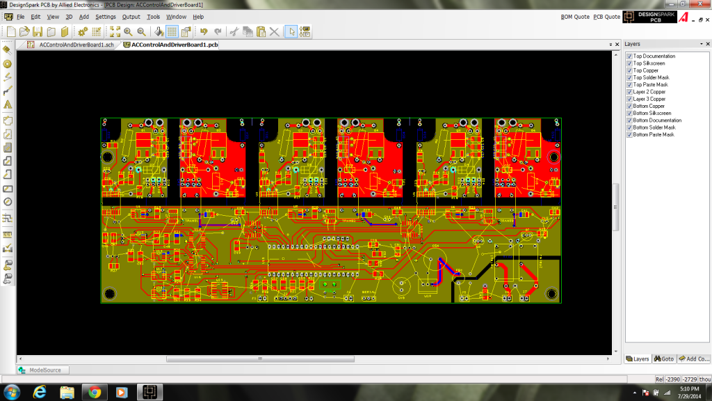
The surface mount caps/resistors are all 1210 size, with a big base pad, so it will be easy to solder them by hand. |
|
|
|
|
The Following 3 Users Say Thank You to MPaulHolmes For This Useful Post:
|
|
|
07-30-2014, 12:03 AM
|
#855 (permalink)
|
|
Master EcoModder
Join Date: Sep 2010
Location: Saskatoon, canada
Posts: 1,488
Thanks: 746
Thanked 565 Times in 447 Posts
|
AWESOME picture!
Quote:
Originally Posted by MPaulHolmes
... The nice thing is, I've made so many mistakes before, that it's easy to know what I will mess up now...
|
I think the ability to predict where mistakes may be is called EXPERIENCE! |
|
|
|
|
The Following User Says Thank You to thingstodo For This Useful Post:
|
|
|
07-30-2014, 12:04 AM
|
#856 (permalink)
|
|
EcoModding Lurker
Join Date: Apr 2014
Location: seattle
Posts: 23
Thanks: 33
Thanked 11 Times in 10 Posts
|
Just intime for a fall quarter project. Sweeeeet
|
|
|
|
|
07-30-2014, 02:18 AM
|
#857 (permalink)
|
|
EV Connoisseur
Join Date: Aug 2010
Location: Amsterdam
Posts: 309
Thanks: 70
Thanked 109 Times in 90 Posts
|
Aah.. nice.. I see a serial connector on there... is it 3.3V?
|
|
|
|
|
The Following User Says Thank You to flores For This Useful Post:
|
|
|
07-30-2014, 08:40 AM
|
#858 (permalink)
|
|
PaulH
Join Date: Feb 2008
Location: Maricopa, AZ (sort of. Actually outside of town)
Posts: 3,832
Thanks: 1,362
Thanked 1,202 Times in 765 Posts
|
Flores, where does the 3.3v have to be? Is it the 2 pins leaving the board? (Ignoring the ground pin)
|
|
|
|
|
07-30-2014, 01:05 PM
|
#859 (permalink)
|
|
EV Connoisseur
Join Date: Aug 2010
Location: Amsterdam
Posts: 309
Thanks: 70
Thanked 109 Times in 90 Posts
|
Quote:
Originally Posted by MPaulHolmes
Flores, where does the 3.3v have to be? Is it the 2 pins leaving the board? (Ignoring the ground pin)
|
The serial tx level needs to be max 3.3v |
|
|
|
|
07-30-2014, 01:06 PM
|
#860 (permalink)
|
|
EV Connoisseur
Join Date: Aug 2010
Location: Amsterdam
Posts: 309
Thanks: 70
Thanked 109 Times in 90 Posts
|
I thought the ac would be almost identical to the dc, but clearly it isn't.
|
|
|
|
|


